The cooling system of the GT40 MKIV: challenges and solutions


Planning and designing the cooling system for my Ford GT40 MKIV was one of the more complex tasks I faced. The limited space in the engine compartment, the requirements of a powerful V8 mid-engine and the desire to preserve the original appearance of the vehicle posed particular challenges.
Positioning the coolers and pipes
A major problem in the design of the cooling system was the extremely small engine compartment. A conventional mechanical water pump simply wouldn’t fit. After intensive research, I decided to switch to an electric water pump. The forum recommended two manufacturers who offer pumps for high-displacement engines: Pierburg (Germany) and Davies Craig (Australia).
Both manufacturers kindly provided me with CAD data, which helped me with the planning. I would have liked to use the Pierburg pump, but it could not be integrated into the overall system in a flow-optimized way. In the end, my choice fell on the Davies Craig EWP150the manufacturer’s most powerful pump, which is often used in conjunction with US engines. The technical support from Davies Craig was particularly helpful and provided me with significant assistance in designing the cooling system.
However, the pump alone was not enough. The EWP150 requires a programmable controller and suitable accessories for integration into the cooling system. Davies Craig offers complete installation kits that can be obtained from various dealers in Germany or directly from Australia. Another advantage of this solution is the ability to control the cooling system efficiently and individually.
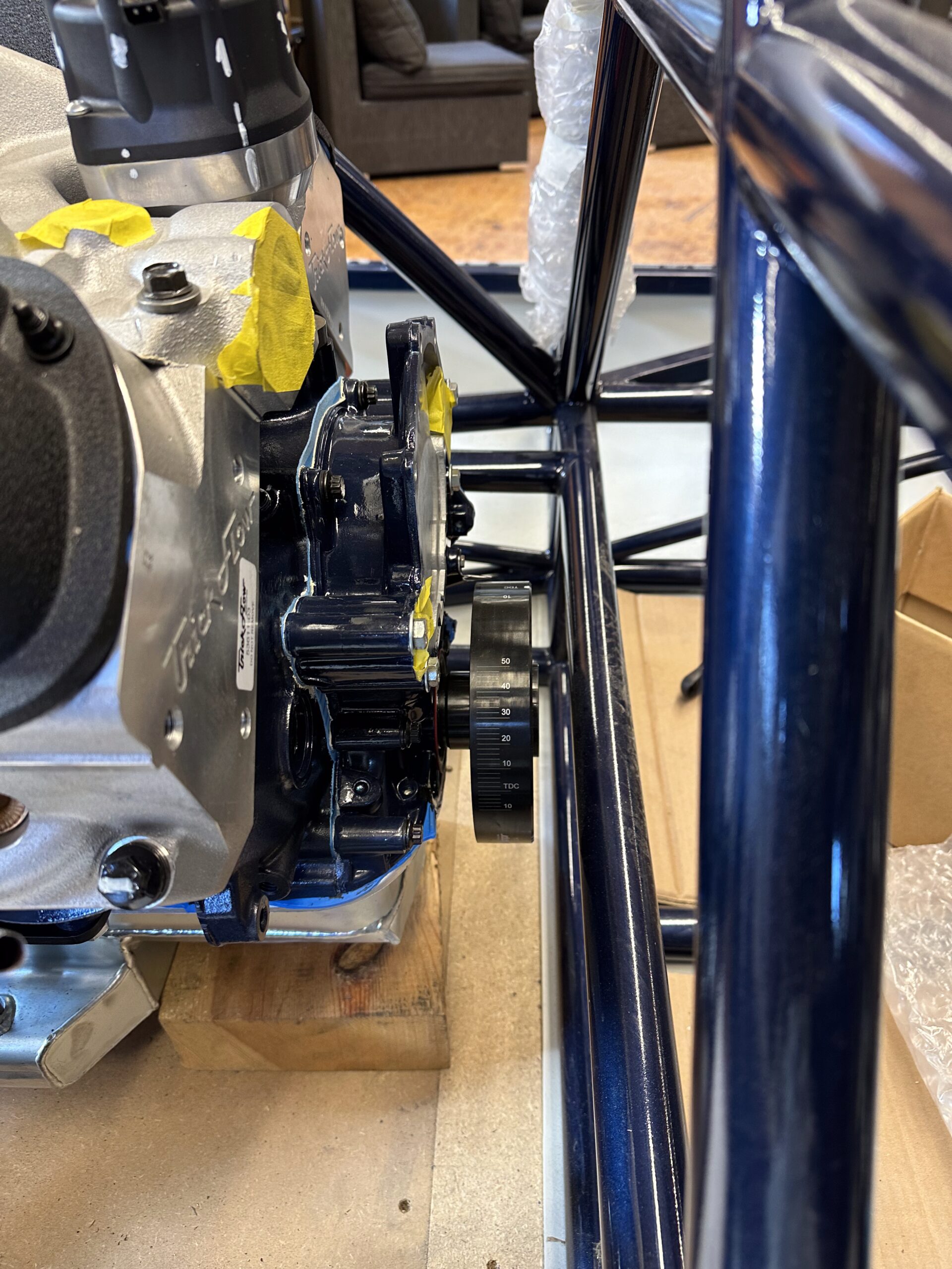
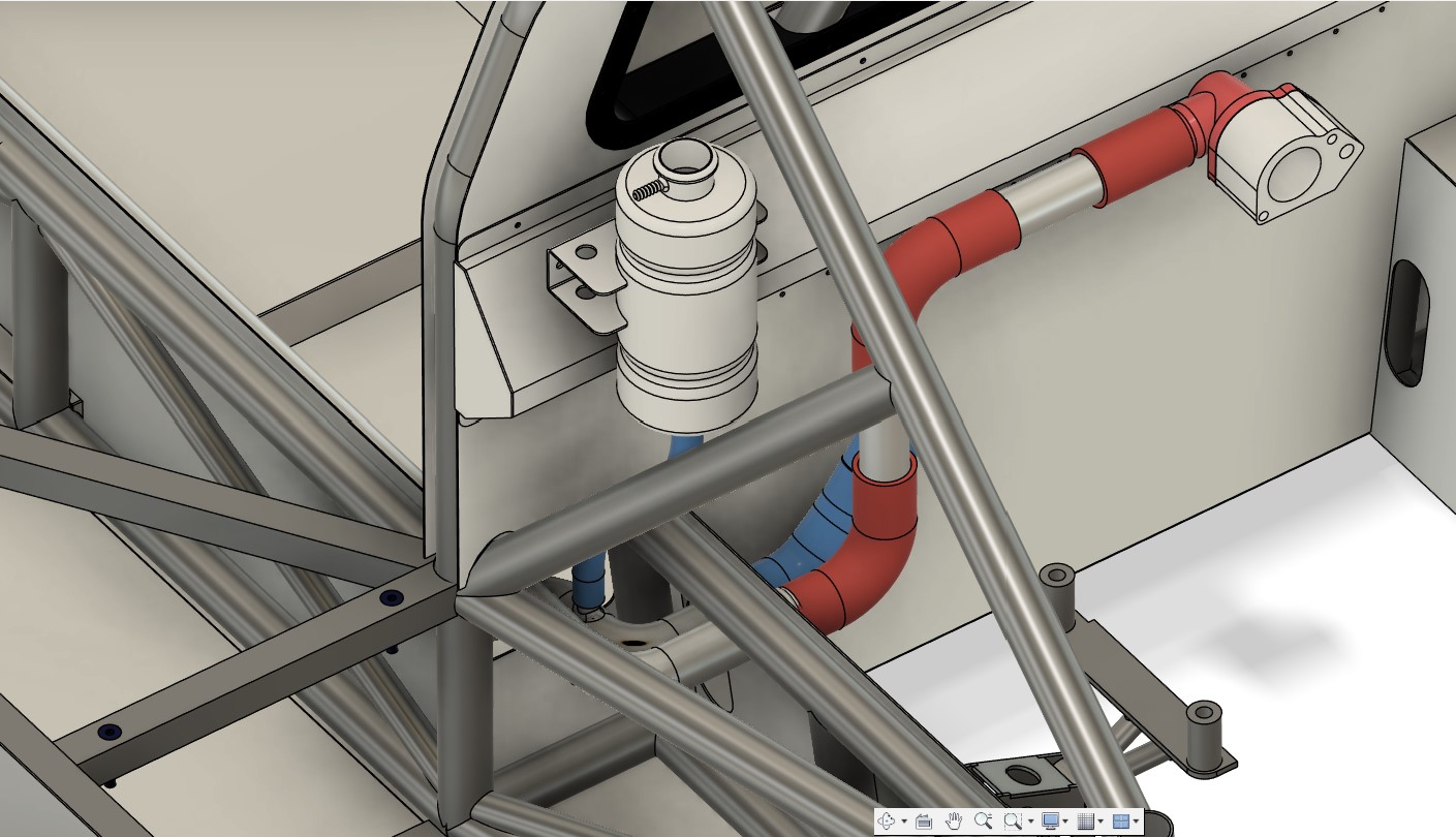
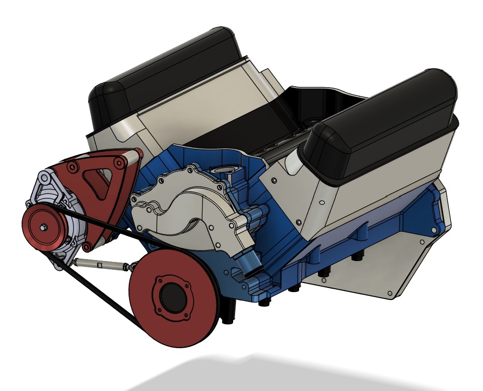
An additional component is the connection to the engine.
As I couldn’t install an original water pump, I had to design my own cover, which is installed instead of the normal water pump and creates the hose connection to the pipes for the electric water pump. This was also a CNC milled part, which I redesigned several times to reduce the milling costs.
Challenges in the design of the cooling system
There were many decisions to be made when designing the cooling system:
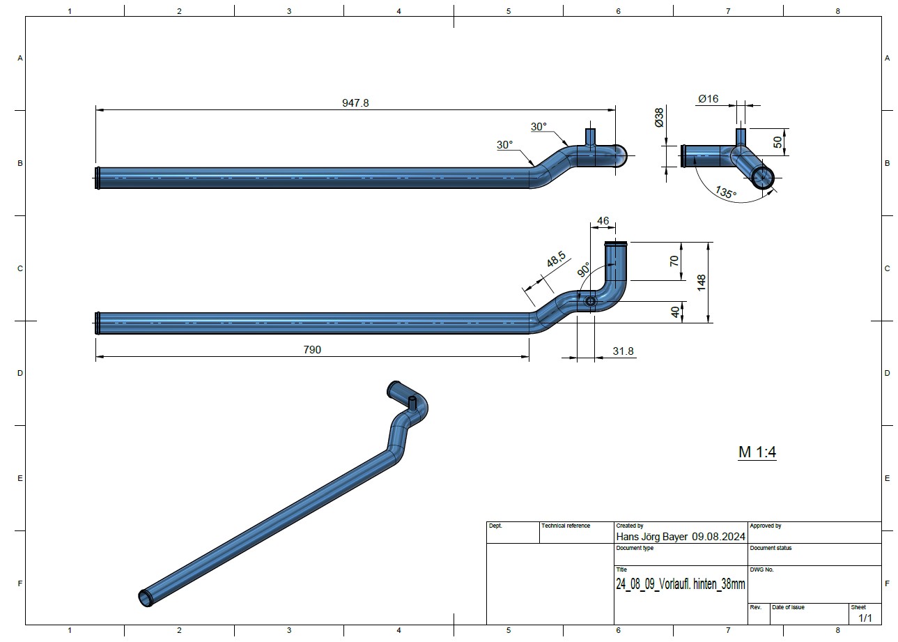
- Diameter of the cooling water pipes: These must be dimensioned in such a way that they ensure a sufficient flow rate without taking up too much space. I opted for 38 mm, with a wall thickness of 2 mm, all made of aluminum.
- Choice of material: Durability and low weight were decisive factors in the choice of aluminum tubes.
- Integration of a heater: In the end, I decided not to install a heater, as this is a pure racing car. Instead, I plan to install an electrically heated fan to ventilate the windshield. However, I haven’t thought about this in detail yet.
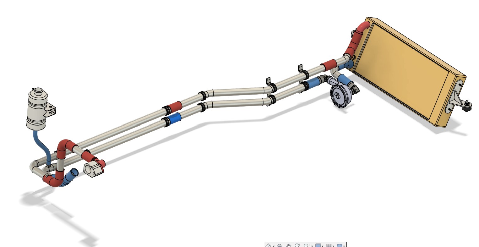
- Positioning the water pump: There are two different opinions on this: Some experts recommend positioning the pump as close to the radiator as possible, while others advocate placing it as close to the engine as possible. This discussion is particularly relevant for vehicles with a mid-engine, as the distance from the radiator to the engine is almost three meters. After consulting with both pump manufacturers, I decided to follow the recommendation to mount the pump as close to the radiator as possible. The reasoning: The suction power of the pump is weaker than the pressure power, which is why the suction path should be kept as short as possible. As I am not an expert in this field myself, I followed the manufacturer’s recommendation.
- Connecting pieces and hoses: There are several transfer points and changes of direction in the cooling circuit. First of all, I determined the available silicone hose elbows, so what are the standard angles. I use straight silicone hoses from Viper-Performance, obtained from BAT-Motorsport, as well as bends at 30°, 60° and 90°. I then used these in CAD along the projected path of the radiator lines and then constructed the necessary short connections from straight and bent pipe sections. In this way, I was able to dispense with complex special hoses. Motorsport double hose clamps round off the whole thing.
My philosophy was clear: as simple as possible, as effective as necessary. A minimalist system is less prone to problems and remains easy to maintain.
The characteristic radiator line of the GT40 MKIV
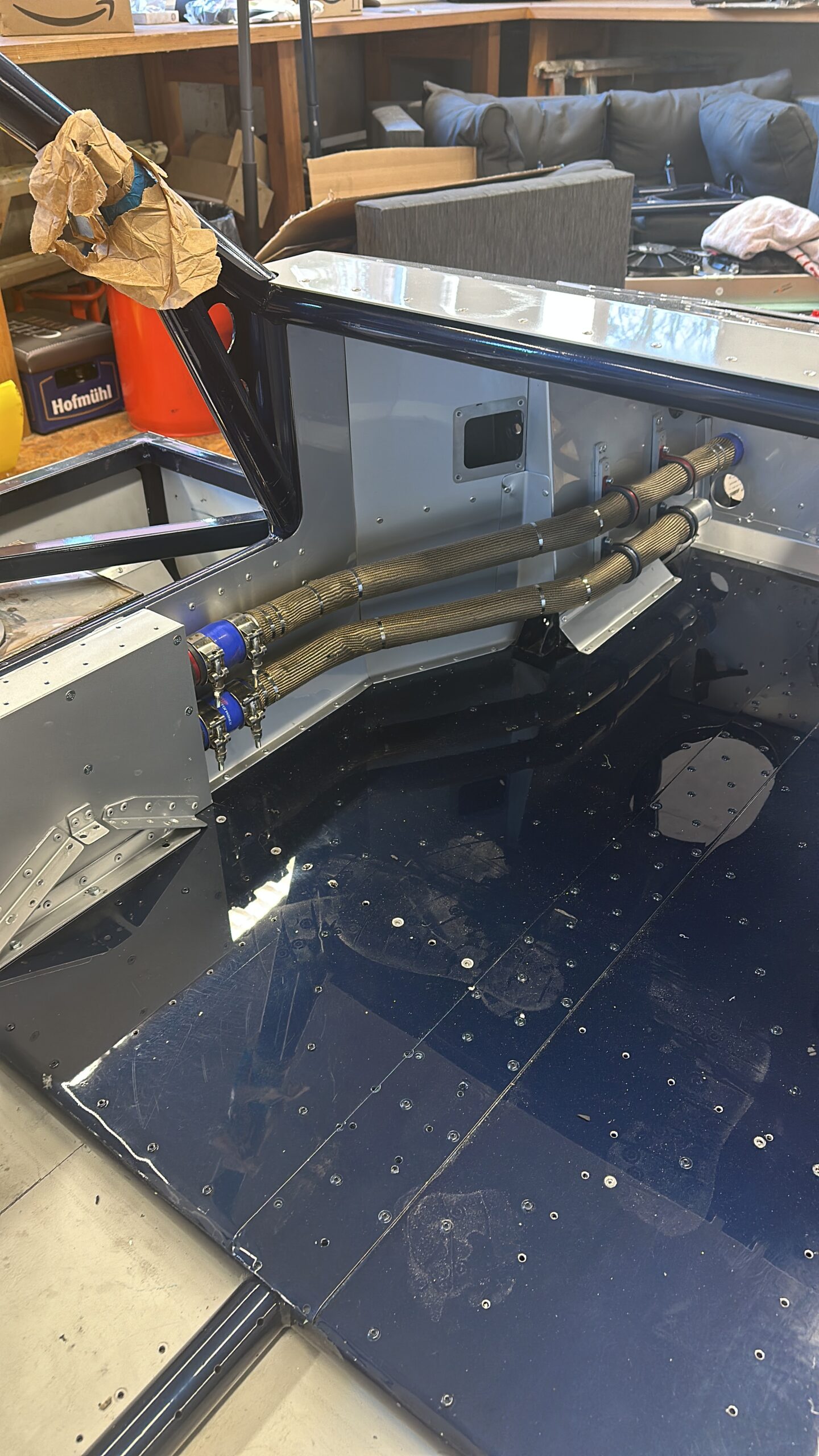
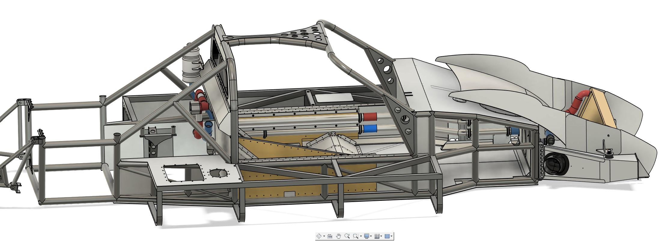
Another special feature of all GT40 models are the long cooling water pipes that run from the engine compartment to the front radiator. In the GT40 MKIV, they run along the left-hand interior side wall and are a striking feature of the design. I really wanted to preserve this iconic look.
As the pipes have several bends, I split them so that they could be dismantled if problems arose. For this reason, the panels of the passenger seat had to be designed to be screwable so that the pipes could still be accessed in the finished car. The majority of the pipes run inside the side wall of the passenger seat, which resulted in a complicated construction of the seat. This meant that the space available towards the rear of the engine compartment was extremely tight.
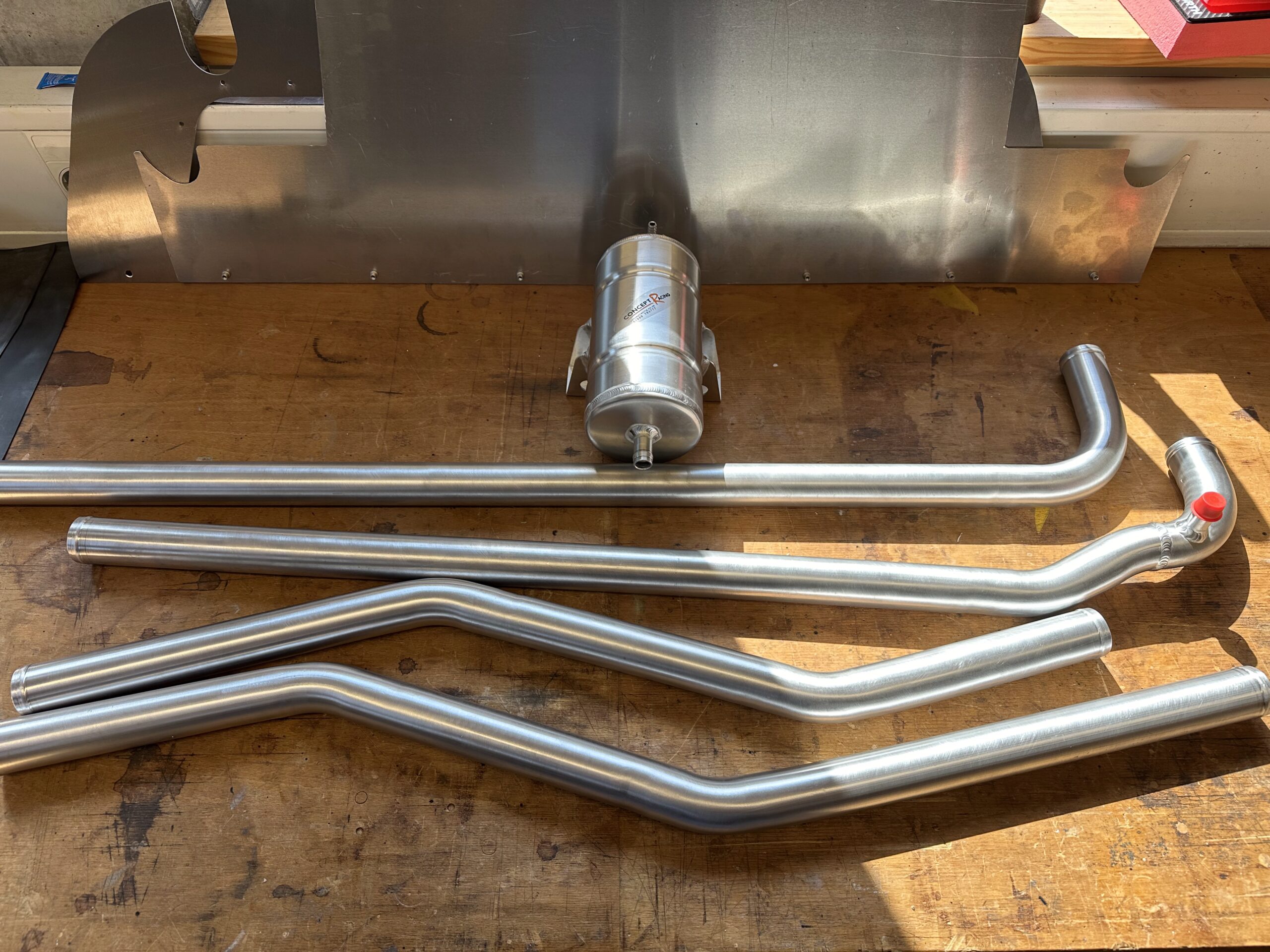
It was also a challenge to find an affordable manufacturer for the pipes and the radiator who could produce such complex parts. I found what I was looking for in England at Concept Racing. The designer there, Clare, was super nice and helpful. I sent them precise 2D drawings and 3D models and received parts that fit perfectly. However, one tube required a short video that I created in CAD to show how it needed to be bent and welded. This 10-second movie avoided tedious mistakes – cheers to the possibilities in Fusion 360!
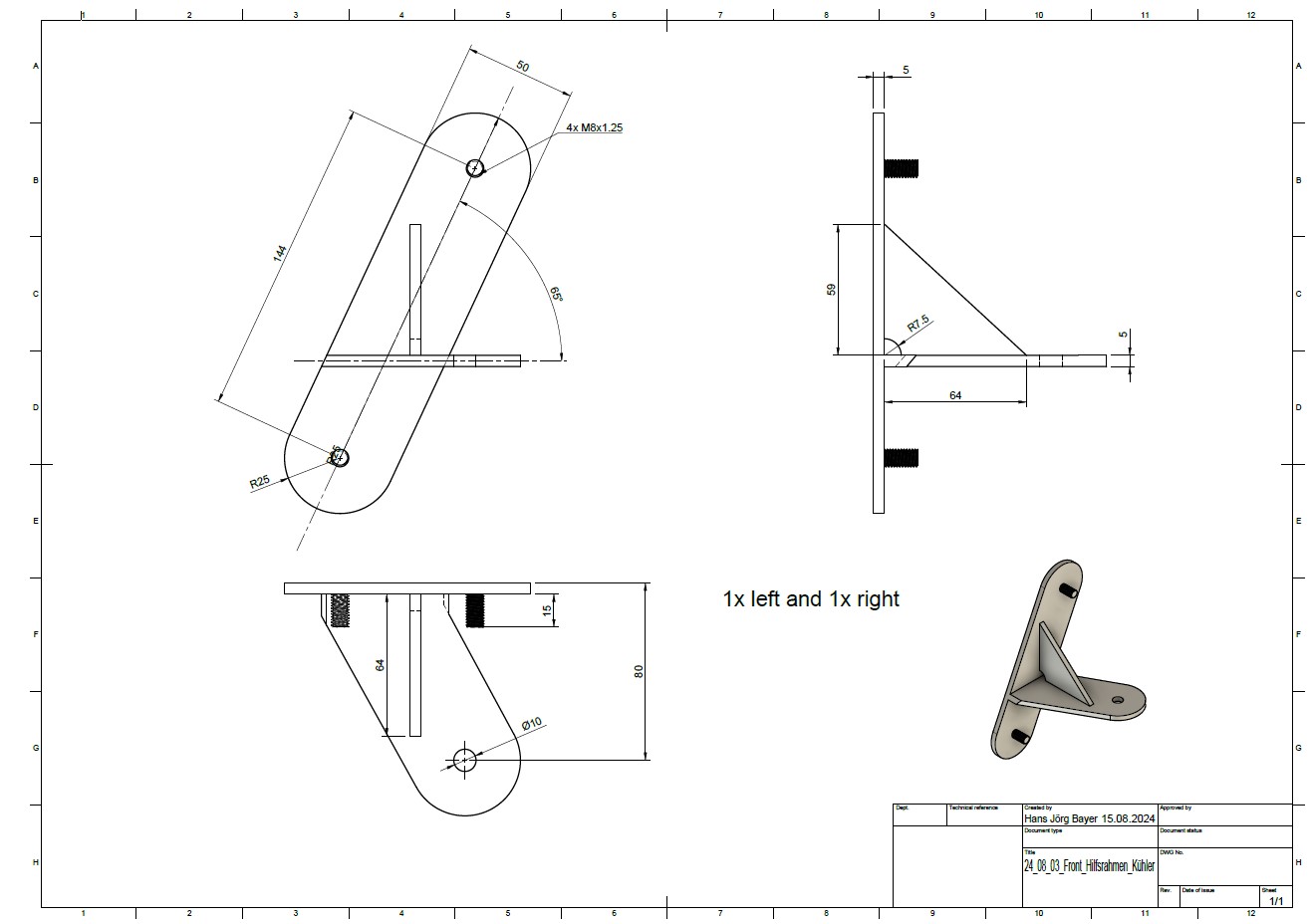
The choice of cooler
I also relied on Concept Racing’s expertise when selecting the radiator. The length and width of the radiator had to make optimum use of the limited space in the vehicle without compromising efficiency. The thickness of the radiator also played a decisive role. While the original radiator was almost 100 mm thick, modern high-performance grilles today allow a comparable cooling performance with significantly smaller dimensions. That’s why I opted for a thickness of 60 mm, which both saves weight and improves airflow.
The design details such as the position of the connections, the attachment of the radiator, threads for the temperature sensors of the electric water pump, etc. were precisely coordinated.
The design of the air baffles to the radiator was also difficult, as one part is fixed to the frame and the other part is attached to the hinged hood. Here, too, I had to try out several design variants in order to hopefully achieve a good end result.
Conclusion ?
I can’t really come to any conclusions on this subject at the moment, firstly because I haven’t yet bought all the parts, such as the water pump, and secondly because the parts I already have haven’t all been installed yet.
I’ll report later on whether I’ve done everything right….
Leave a Reply
You must be logged in to post a comment.