The basis: from the idea to the digital model


It was clear to me from the outset that I could only really bring the project to life if I first built as complete a CAD model as possible – before I even set a single spot weld. That was crucial for me for two very clear reasons:
- Understanding the complexity and finding solutions
A project like this is incredibly complex, and it was only through a digital model that I could really understand how everything fits together. This was the only way I could develop solutions for all the problems that inevitably arise – without realizing later on that something doesn’t fit. Of course, there were still mistakes, and quite a few – often due to carelessness, a lack of knowledge or simply my impatience, which sometimes made me rush ahead too quickly. But that’s part of it for me. After 4 years of building so far, I’ve become a little more humble. - The need for efficient production
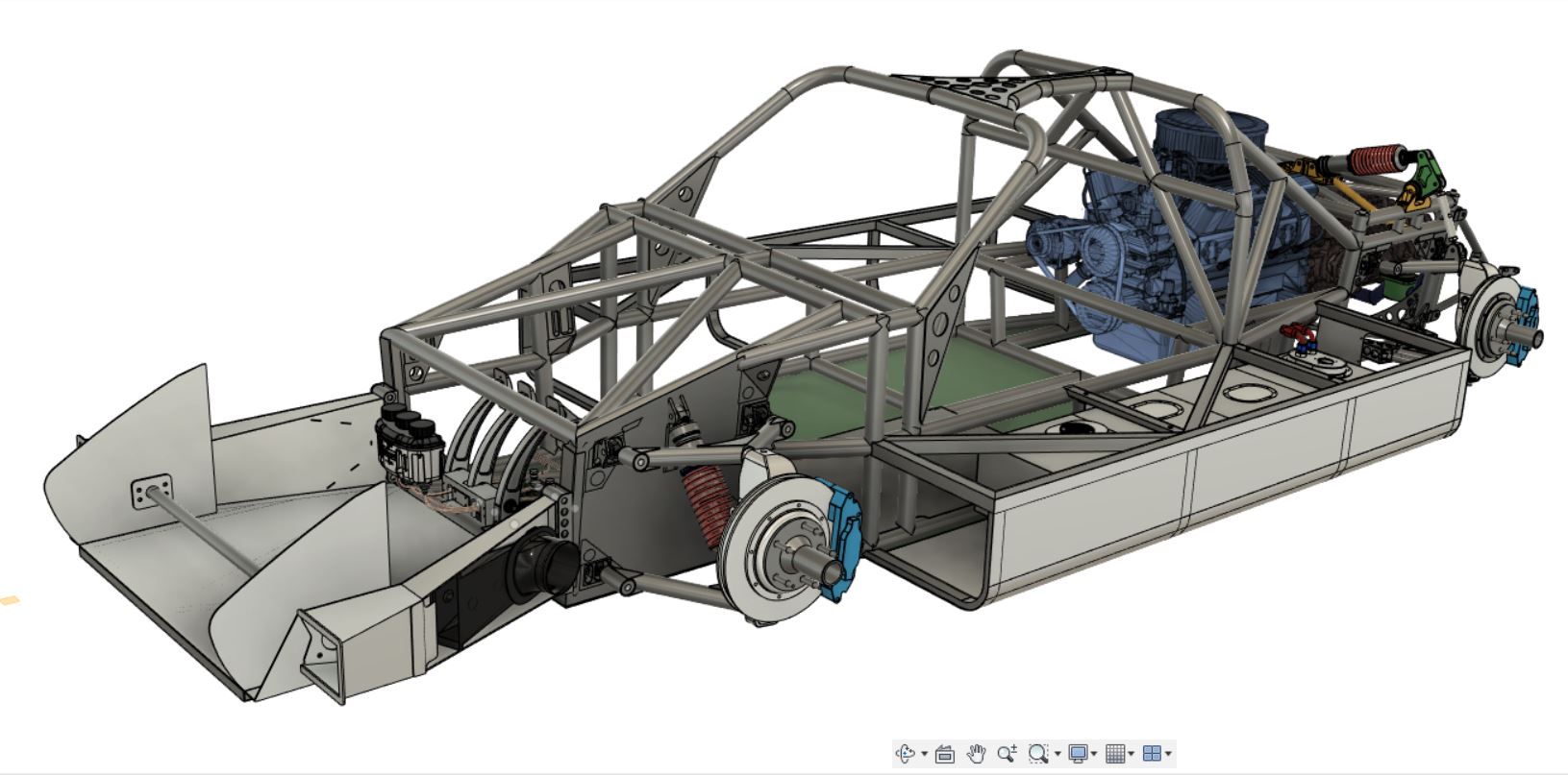
Most parts of the chassis cannot be produced efficiently without a CAD model. Whether it’s CNC-milled parts, turned parts or laser-cut components – without the digital model, production would take much longer and be much more error-prone.
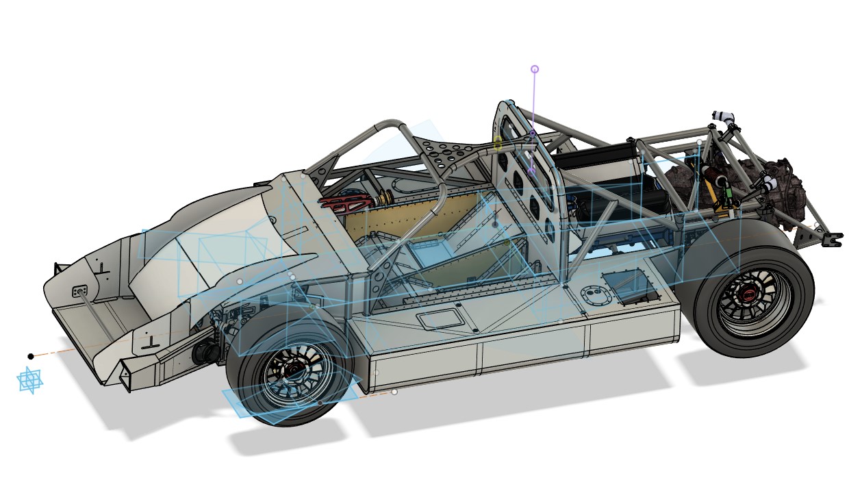
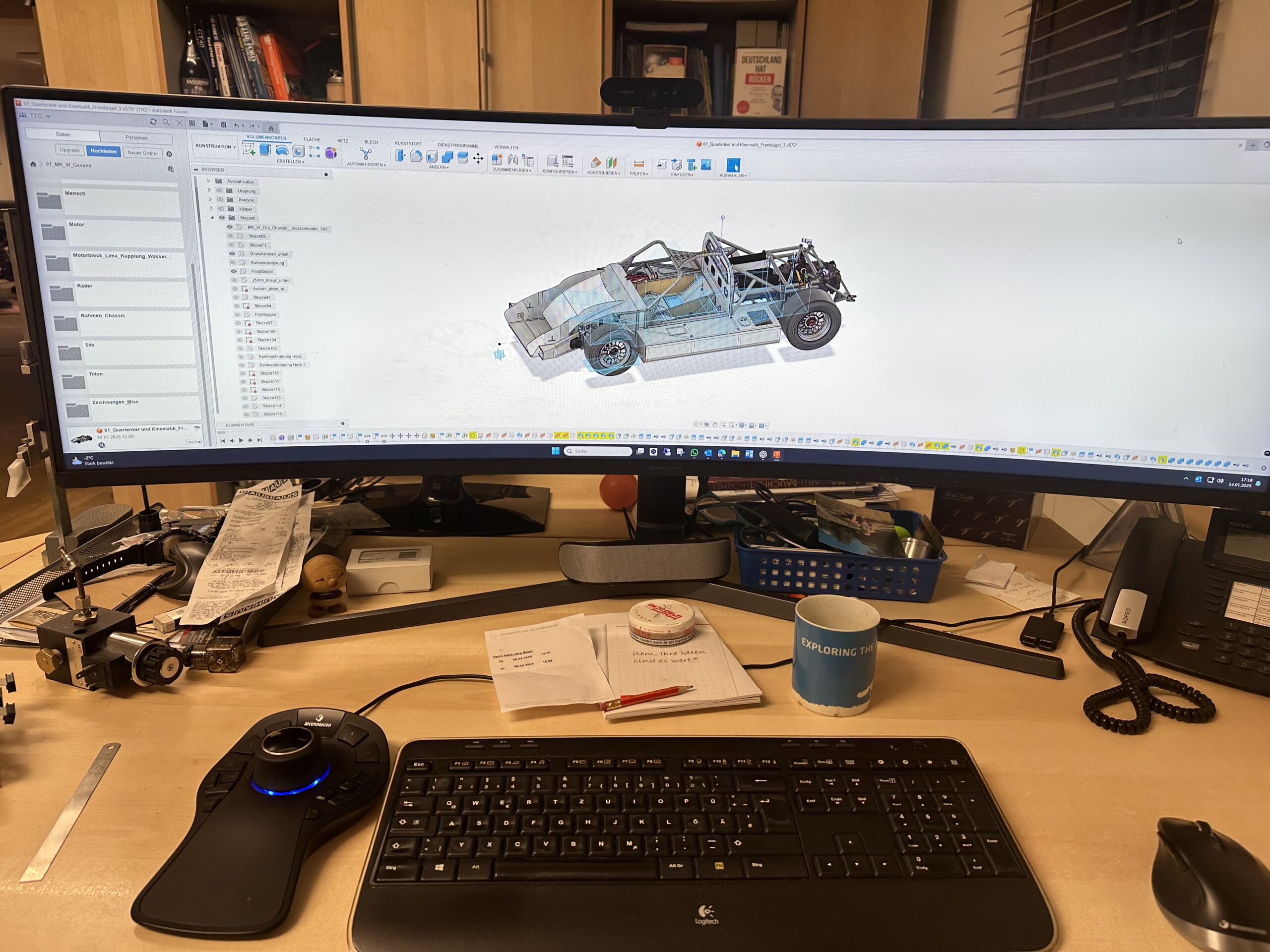
In the end, only with a CAD model is it possible for me to have an overview of the vehicle in its entirety and ensure that everything fits together seamlessly. This allows me to see all the details of the car before I start building it and to take measurements during construction, etc.
1. digitization of dimensions and data (plans, sketches).
The start of my CAD work was very simple: I began with a 2D plan view and side view to determine the basic dimensions of the vehicle. I used old documents that Ford had submitted when I registered for the Le Mans race. These included basic dimensions such as wheelbase, track width and the overall vehicle dimensions – in other words, everything you need for the initial rough dimensioning.
Using these values, I sketched the vehicle in a simple 2D representation in order to have the most important dimensions clearly laid out on a single document. The advantage of this approach was that I immediately got a clear overview without having to dive straight into the complexity of 3D modeling.
I used TurboCAD for these first steps, as the program offers particularly strong 2D functionality. It allowed me to draw the dimensions precisely and quickly, which was essential for this basic phase. I was able to use this simple template to build everything else later and develop the details step by step.
(You can find an overview of the software I used and still use for the construction here in this article)
2. sources of errorand initial stumbling blocks
My problem was a fundamental one that only really caught up with me when I was building. At the beginning there was a crucial question: Do I design the car from the outside in or vice versa?
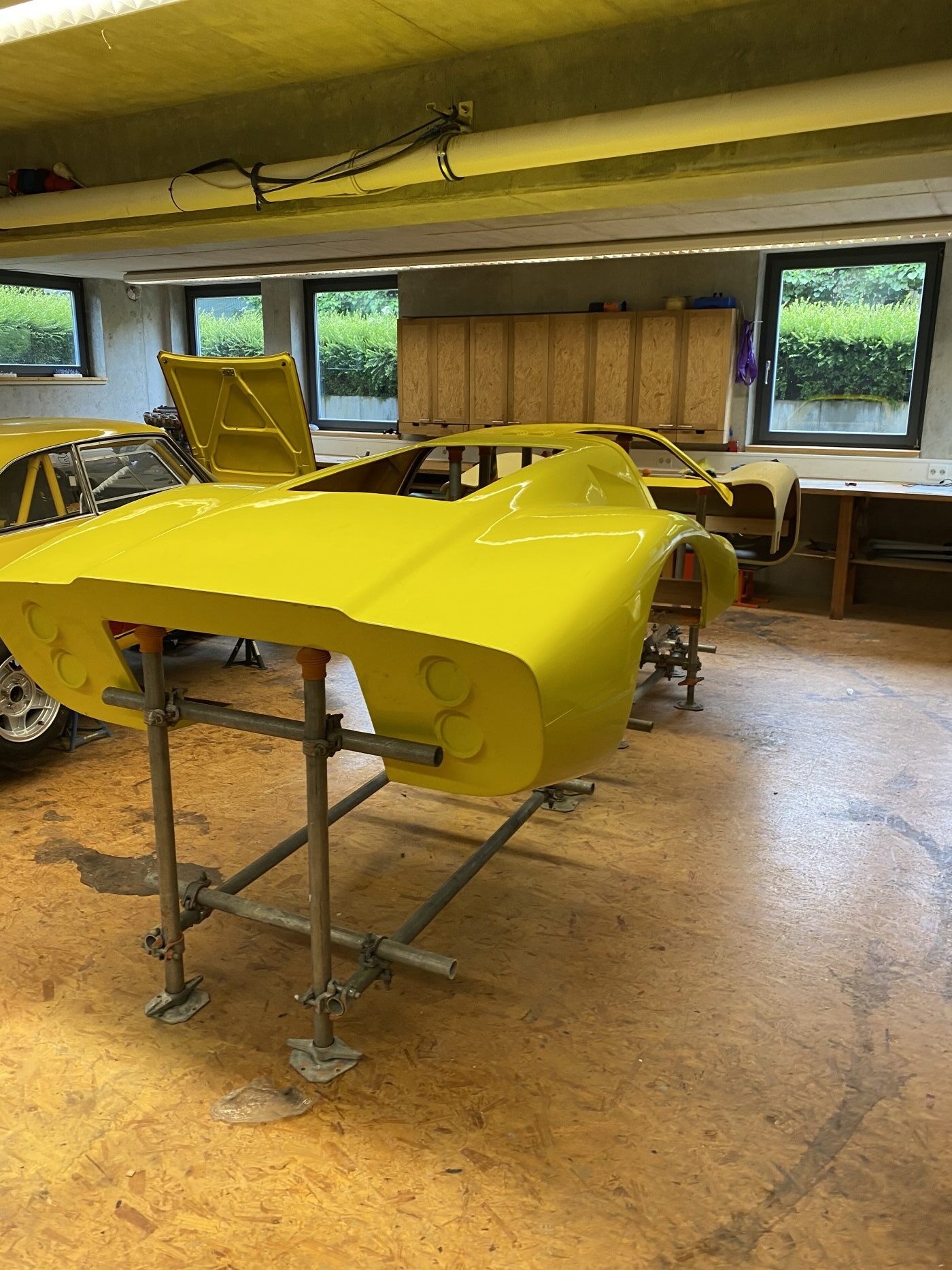
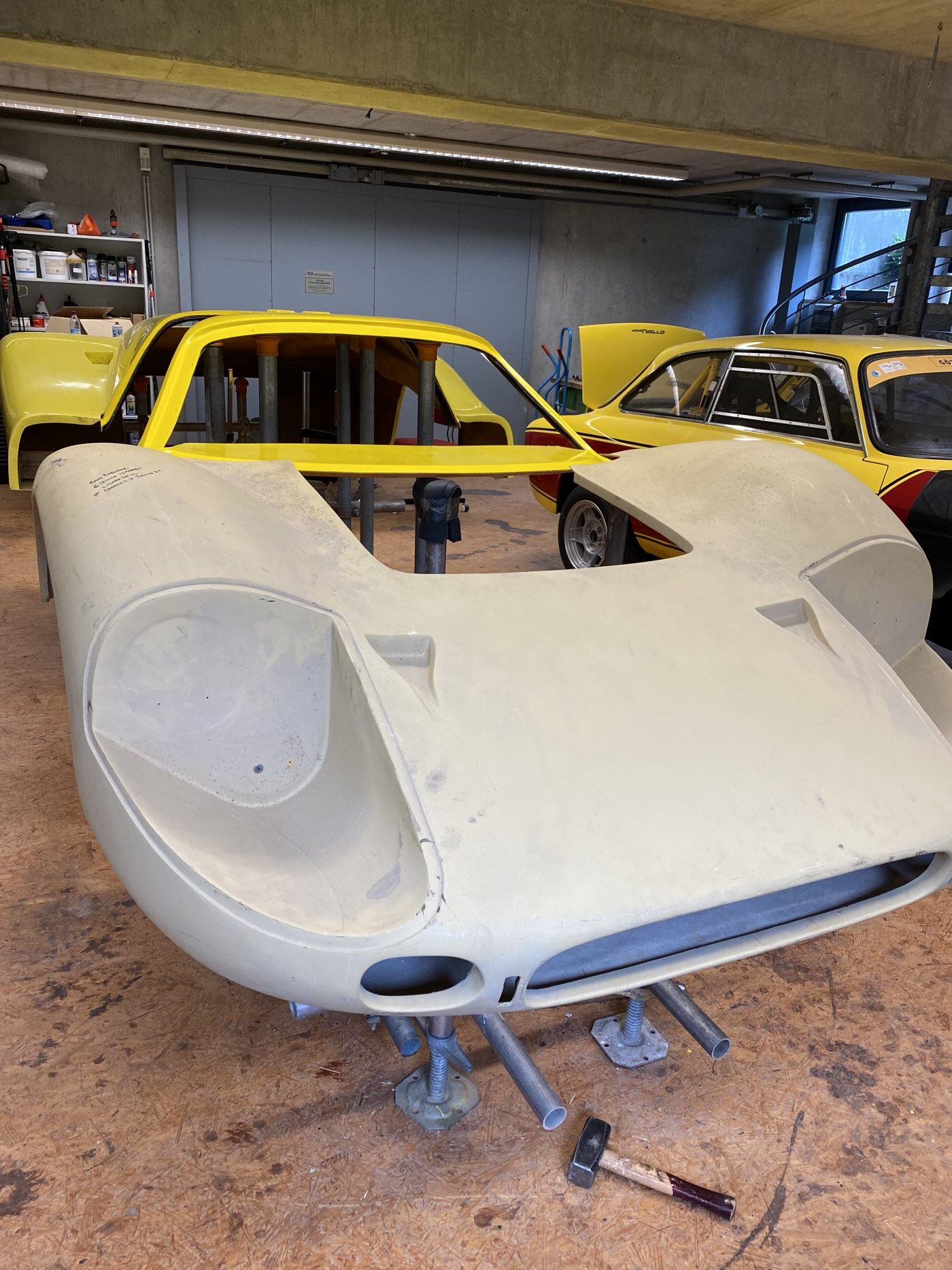
For me, this was not really a question at first, because it seemed logical to construct from the outside in. Why? Quite simply – I already had all the necessary GRP body parts, and it was the first step for me to digitize these parts. My friend, who is a scaffolder, had kindly provided me with some scaffolding parts from the house construction, which I used to build a frame – thanks Lars!
I then attached the body parts to this frame and inserted the windshield to align the parts as well as possible.
I discovered that the components could be aligned with each other, but it was unclear whether this alignment was actually correct in relation to the chassis.
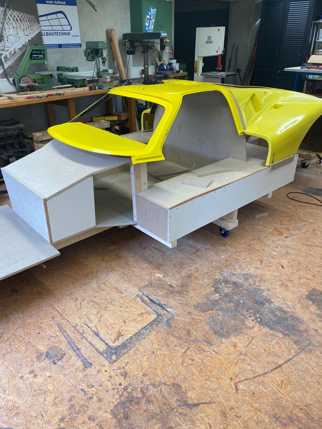
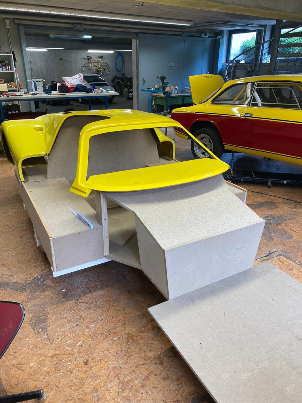
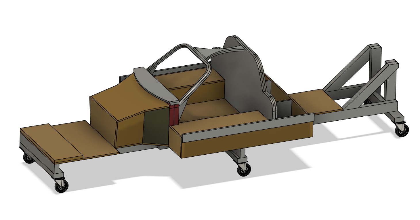
To solve this problem, I rebuilt the original aluminum honeycomb sandwich chassis from 19 mm chipboard. Although this involved considerable extra work and additional costs, the effort was more than worth it for me. I mounted the wooden chassis on a sturdy frame made of wooden beams and fitted it with wheels, which made it mobile. After dismantling the wooden chassis, I was also able to use the remaining frame as a practical platform for further assembly.
With this construction I was able to scan the body and thus had a solid basis. Once I had roughly processed the scan, I was able to integrate the body into my CAD model as a reference. I was always guided by the fact that everything I designed on the frame actually had to fit into the body.
So far, so good – but it later turned out that this approach was not the best decision. It wasn’t until last year, when I was working on the steering and the seating position, that I realized that some tubes were in the way, as I had already finished the tubular frame. That’s why I had to retrofit a cut-out in the frame for the steering gear. However, finding suitable positions and mounting points was a particular challenge when designing the seats, as the space was severely restricted by the previously defined body layout. These problems cost me a lot of time, which I could have invested better in retrospect – but more on that later in the relevant chapter.
3.conclusion
Today, I would proceed the other way round: First determine the basic dimensions, then place the body in CAD and then determine the seat and steering wheel positions. I would only start constructing the frame once these parameters have been defined.
My friends in racing still laugh at me, because for them it would have been a matter of course to proceed in this way from the very beginning. Well, you’re always smarter afterwards – but considering that this was my only major mistake in the first three years, it somehow gives me hope
Leave a Reply
You must be logged in to post a comment.