Suspension: hub carrier and wishbone
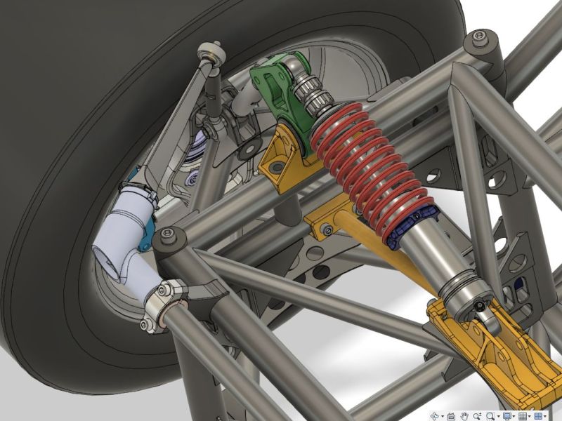
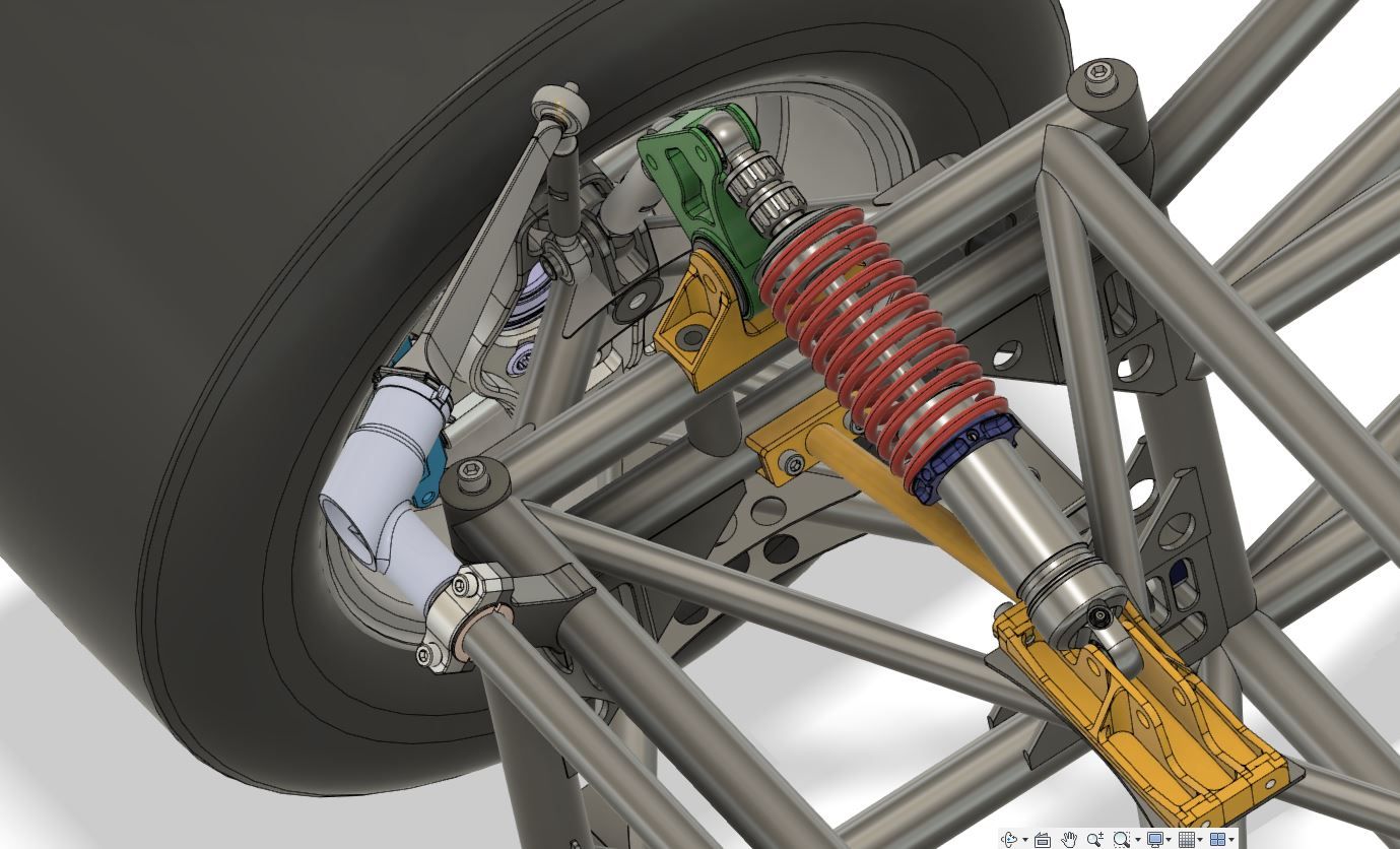
The wheel suspension of the GT40 MKIV was one of the biggest challenges in the design of my vehicle. The extremely tight space conditions, caused by the small but wide 15-inch rims, made particularly clever and precise planning necessary. Numerous design approaches were tested, rejected and revised until I finally found a solution that I was really happy with. The result is a technically mature, weight-optimized and extremely resilient wheel suspension that meets the requirements of a high-performance vehicle.
Design of the hub carrier and wishbone
Clearance and kinematics
The basis of the car’s suspension is the chassis kinematics, which defines the six pivot points of the wishbones – four on the chassis and two on the hub carrier. These fixed points are essential for driving behavior and are defined in the kinematics. So I had to build my entire design around these points, taking many factors into account:
- The limited inner space of the rim
- The position of the mounting points for the steering lever and brake caliper
- The wheel bearing used is from the Audi R8.
- The position of the frame tubes
- The maximum steering angle required
- The necessary freedom of movement for all components under load
I ran through many designs in CAD, but it was only with extensive FEM simulations that I was able to develop a structure that works both mechanically and geometrically.
hub carrier: high-strength aluminum construction
The Hub’s are among the most complex components of the car’s suspension. I decided to use high-strength 7075 aluminum, which is CNC-milled. The shape was a constant balancing act: on the one hand, it should be as light as possible, but on the other hand, it should not lose stability. A design that was too delicate would have increased the risk of breakage, while an oversized construction would have added unnecessary weight. In the end, I found a geometry that was optimized by FEM calculations and offered an ideal balance between stability and strength.
In addition, numerous connections such as the mounts for the university ball joints, the connection of the steering lever and the brake caliper mount had to be precisely integrated. In this case, coordination with the wishbone design was particularly crucial to ensure that everything would fit together perfectly later on.
Wishbone: welded lightweight construction
I made the suspension arms out of high-strength 25CrMo4 steel tubing with a diameter of 35 mm and a wall thickness of 2 mm. I thought long and hard about whether aluminum or titanium would be a better alternative, but steel simply offers the best combination of strength, weldability, and ductility – exactly what I need for racing. And it’s affordable… 🙂
The challenge in building the wishbones was mainly in the welding. To precisely maintain the geometry and avoid warping, I made CNC-milled wooden templates. I was able to insert the individual tubes and weld-in sleeves exactly into these and tack them before everything was finally welded. This method proved successful and ensured that the control arms had exactly the dimensions they should have in the end.
Additionally, I integrated some details to save weight and increase stability at the same time:
- 1.5 mm thick gusset plates made of 25CrMo4 to reinforce the highly stressed areas
- Precision welding sleeves made of the same material, with an internal weight-optimized dumbbell shape
- High-quality motor sports uniball joints with play-free pretension, available almost everywhere from the company ASKUBAL.
- High-strength dowel screws that have been additionally machined for the clearance-free assembly of the transverse control arm bearings
The entire process was extremely laborious and took countless hours of planning, testing and optimization. But in the end, I have a chassis design that not only works, but also meets my quality and performance standards.


Leave a Reply
You must be logged in to post a comment.