Seat position and pedals: ergonomics and functionality


The correct seating position in a vehicle like the Ford GT40 MKIV is far more than just a question of comfort – it is crucial for control, safety and driving experience. In this article, I would like to discuss the challenges and considerations that played a role in the design of the seat position, pedals and their integration into the overall structure.
1. determination of the optimum seating position in CAD
As mentioned in the first post, I made a fundamental mistake at the start of the project: instead of first determining the seating position and designing the frame around it, I went the other way round. As a result, I was later forced to make compromises that are still with me today.
One example is the tapering of the frame at the front right, which obstructs my right leg. In addition, I should have positioned the longitudinal tube in the middle of the vehicle floor slightly off-center to allow a more central seating position. Instead, I am now sitting at a slight angle to the direction of travel – a minimal, but nonetheless annoying deviation.
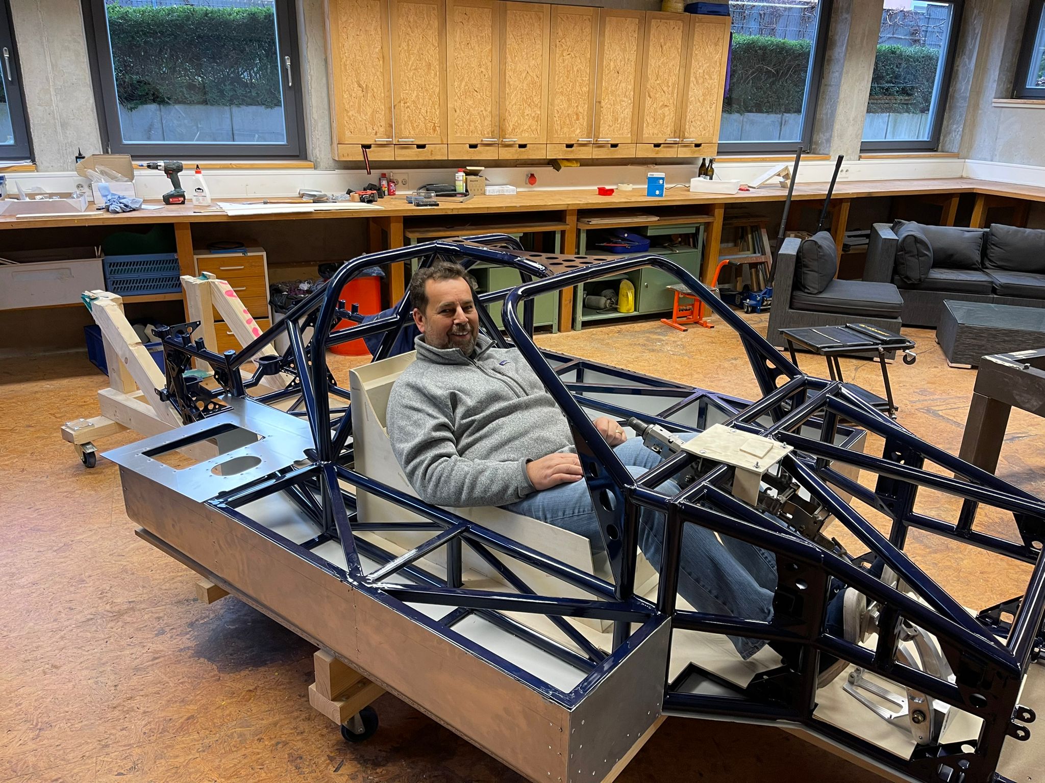
After a long search, I was finally able to find a suitable CAD dummy that helped me to determine the seat position. This dummy enabled me to simulate the driver’s position in CAD and draw initial conclusions about the room layout. On this basis, I designed and built two different wooden seats to test the theoretical planning in practice. The tests showed that it is hardly possible to determine an ideal seating position using CAD alone. You have to test the position in reality – especially to find the compromise between the lowest possible seating position for headroom and sufficient visibility over the dashboard.
I had already provided for additional headroom in the event of a side impact when designing the frame by moving the top of the middle section slightly to the left. This allows my head to slide under this structure in the event of an accident, which could prevent potentially serious injuries.
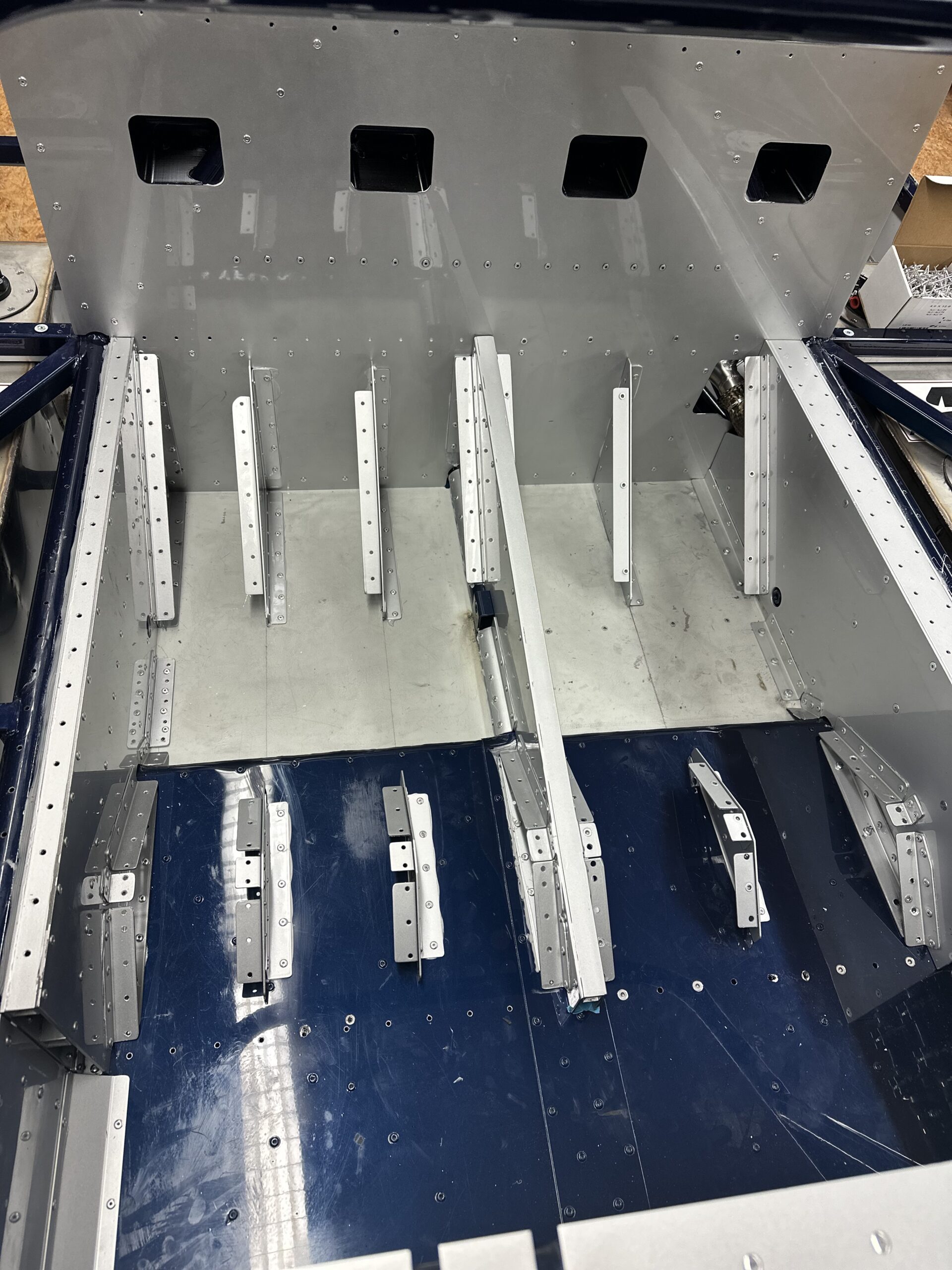
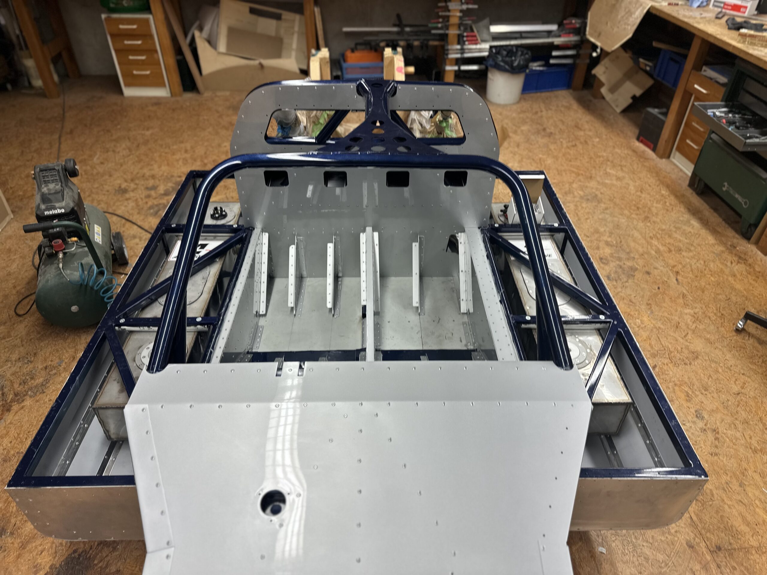
The original vehicle had a one-piece seat shell made of GRP that covered both seats. However, due to the Le Mans regulations, the passenger seat was only a narrow emergency seat in which hardly anyone could sit comfortably. As the production of such a GRP seat shell with mold construction etc. is very cost-intensive, I decided on a different solution: seat shells made of sheet aluminum. This method was also used in other racing cars at the time.
The comfort remains very low with both variants, but that is of secondary importance in a racing car anyway. After foaming the seat shells(here is an example of what this is), adapted to my body shape, I will cover them with black leather – just like the original. Visually, there will be no noticeable difference to the historic GRP seats.
A note for rebuilders: There are GRP seat shells for the Lola T70, which in my opinion are almost identical and could probably fit in the GT40 MKIV. However, I have only found pictures of them and no source of supply or price information. Still, it might be worth looking for these seat shells – maybe someone else will have better luck sourcing them.
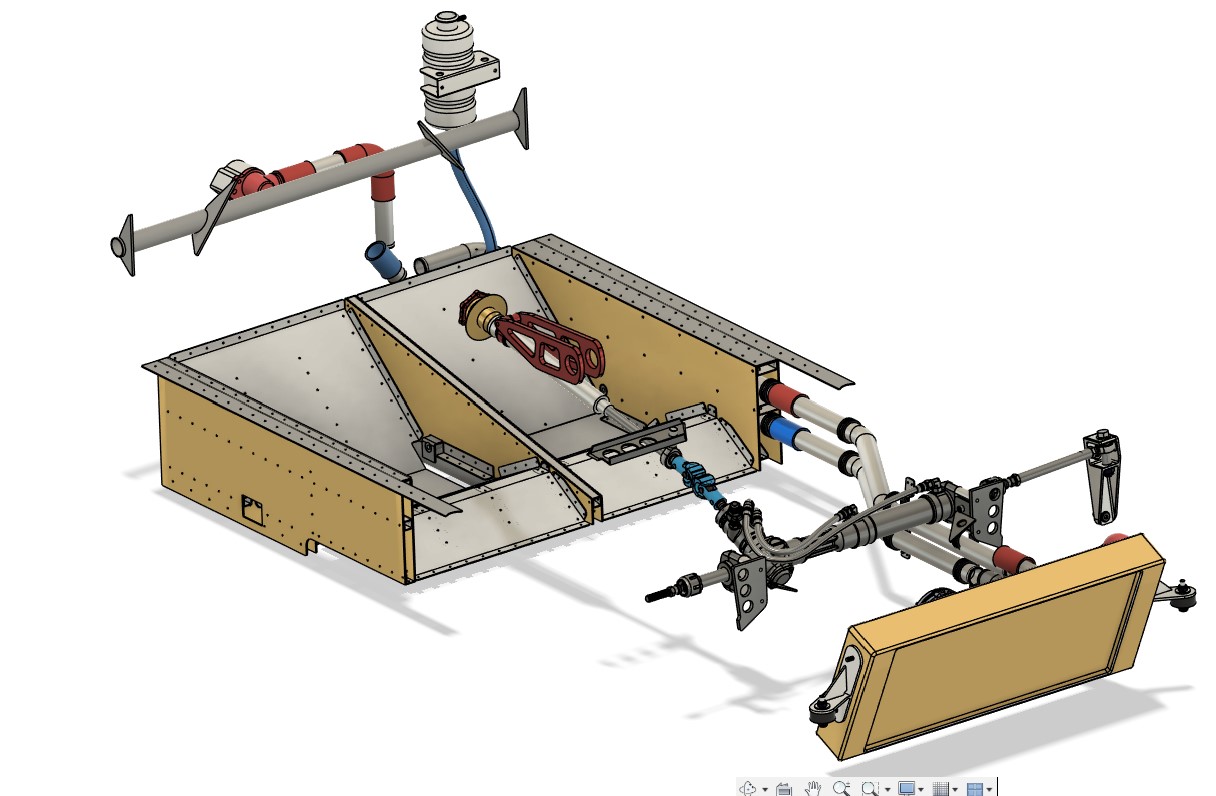
2. design of the pedals with a focus on ergonomics and adjustability
The construction of the pedals was one of the biggest challenges in the footwell of my GT40 MKIV. I extended the frame in the foot area by approx. 15 cm compared to the original – to create more foot space, to better attach the wishbones and the stabilizer bar and to accommodate the steering gear within the frame.
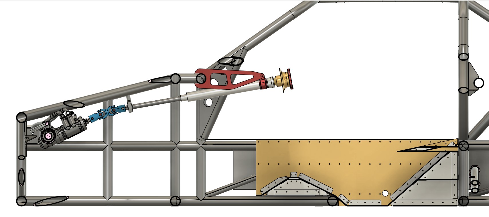
One important factor was the steering: the short levers of the front suspension generate high steering forces. I therefore decided to use a power steering system from racing. However, this solution presented its own challenges, as the steering gear is significantly larger than the original and had to be integrated in such a way that it did not restrict the freedom of movement for the feet.
The original vehicle had suspended pedals with an external cylinder unit. Due to my tubular frame, this design was not feasible for my vehicle. I therefore decided to make the pedals myself from aluminum. It was an intensive process, because space in the footwell is extremely limited – especially if you have size 45 shoes. Every millimeter decision had to be reconsidered to ensure that everything would really fit later on.
To create space for the tips of the shoes, I built a double joint into the steering column. This ensures that the steering column runs more efficiently without protruding directly into the range of movement of the pedals. I also opted for a pedal unit with the brake and clutch cylinders in front of the pedals – a solution that makes good use of the space, but also requires a lot of detail to get it just right.
To be honest, I don’t yet know whether this design will work in practice as I had imagined. The trial assembly will show whether everything harmonizes as I had planned, or whether I will have to fall back on commercially available pedals or even redesign them. In retrospect, I should probably have paid more attention to the integration of the steering gear, pedals and space requirements when planning. But that’s how it is sometimes with a project like this – you learn as you go and not everything works on the first try.
3. seat belts and their integration into the overall structure
The seat belts and their attachment points were a key aspect when designing the overall structure of my GT40 MKIV. Especially in a vehicle with such a low seating position, the correct attachment of the belts is crucial for safety and functionality.
For the planning, I intensively studied the specifications of the Schroth company, which provide very detailed information in the racing section. They define exactly which angles must be maintained for the individual belt parts, which minimum lengths are prescribed and how the attachment to the frame must be designed. These specifications are not only sensible, but also absolutely necessary to ensure safety in the vehicle.
Due to the seating position, I opted for 6-point harnesses from formula racing, which can be specially adjusted to suit your height. These belts provide the necessary safety and prevent you from slipping under the lap belt in the event of an accident.
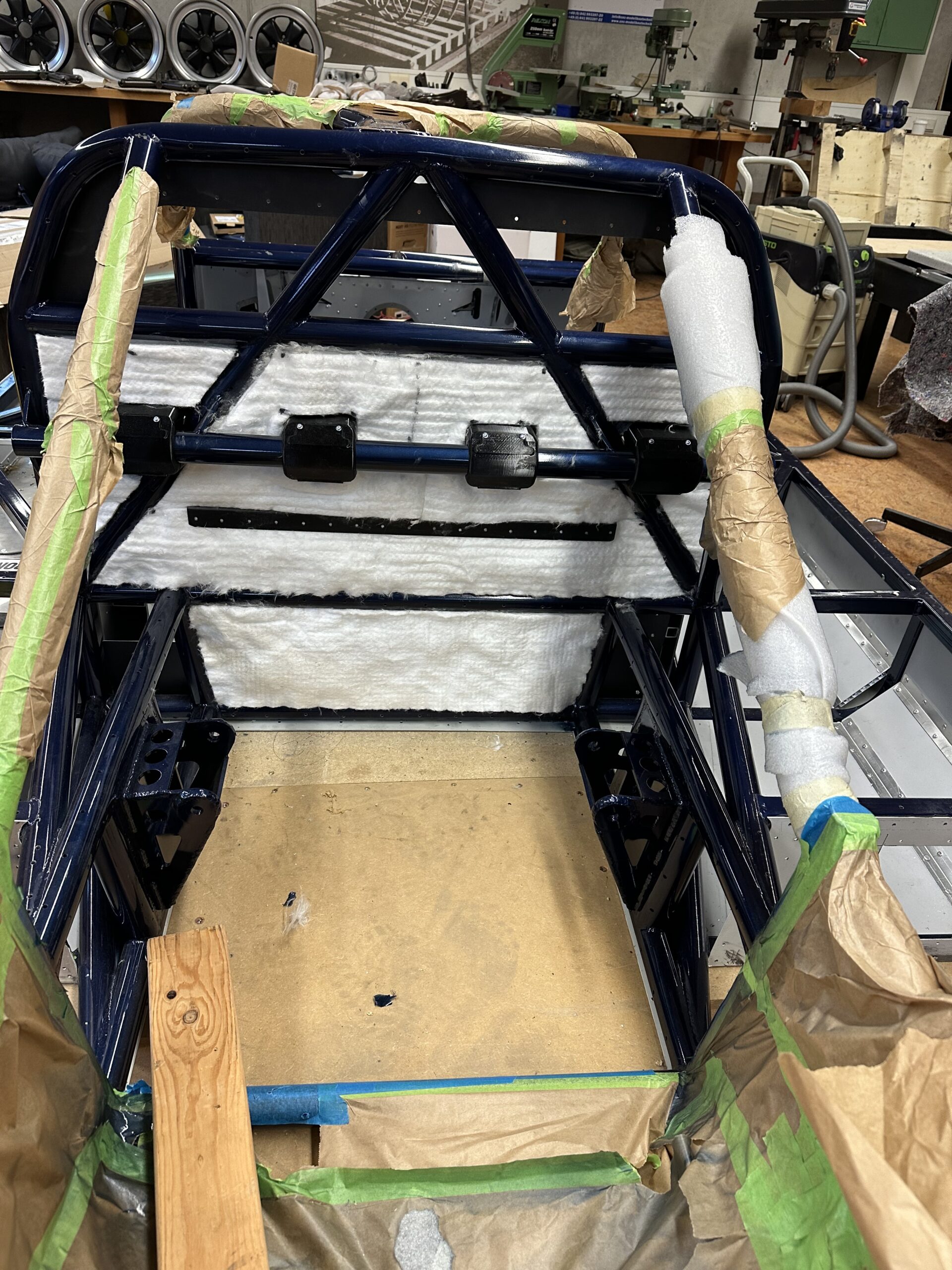
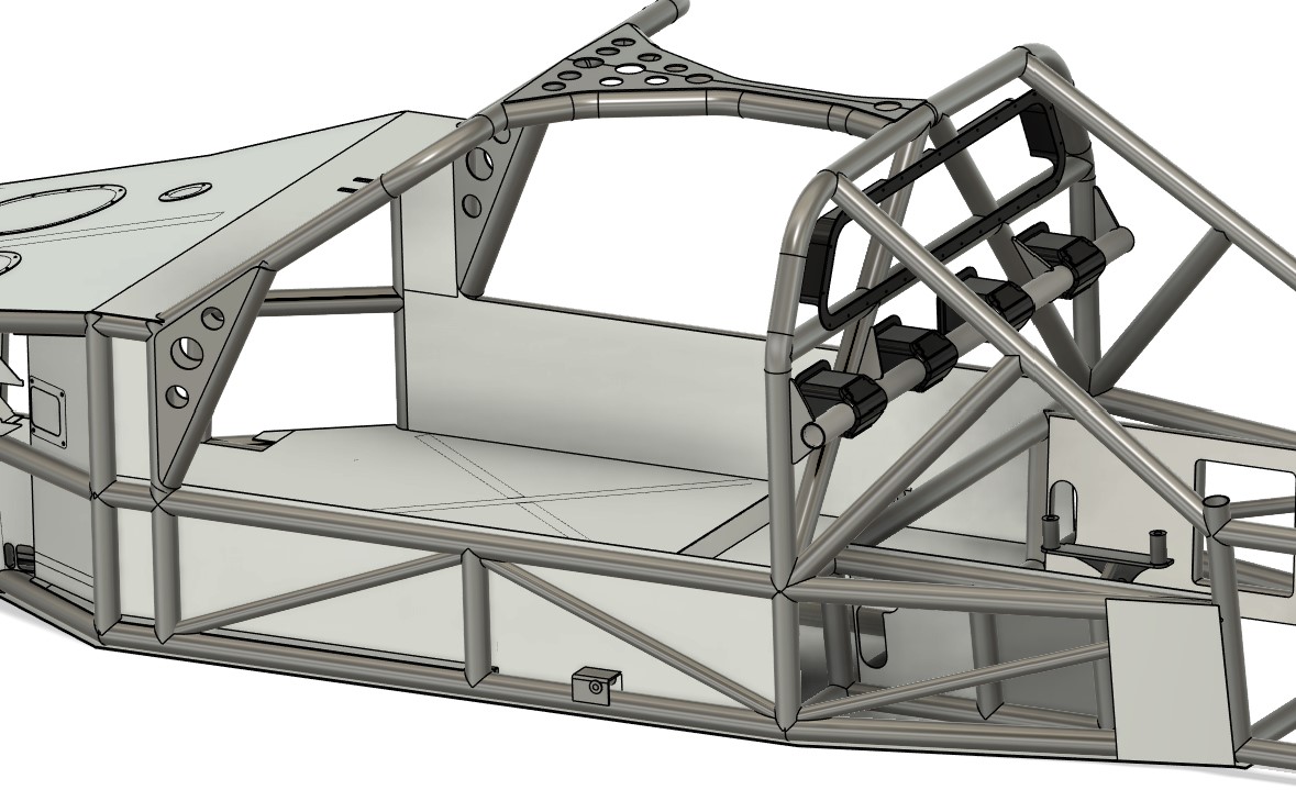
A particular challenge was attaching the shoulder straps. In order to maintain the prescribed minimum distance of 90 mm to the shoulder and the correct angle range of 0° to -20°, I had to attach a special belt tube to the frame. This was a subsequent modification that became necessary because I had only designed the seat shell after the frame had been completed. This mistake caught up with me again and caused additional work.
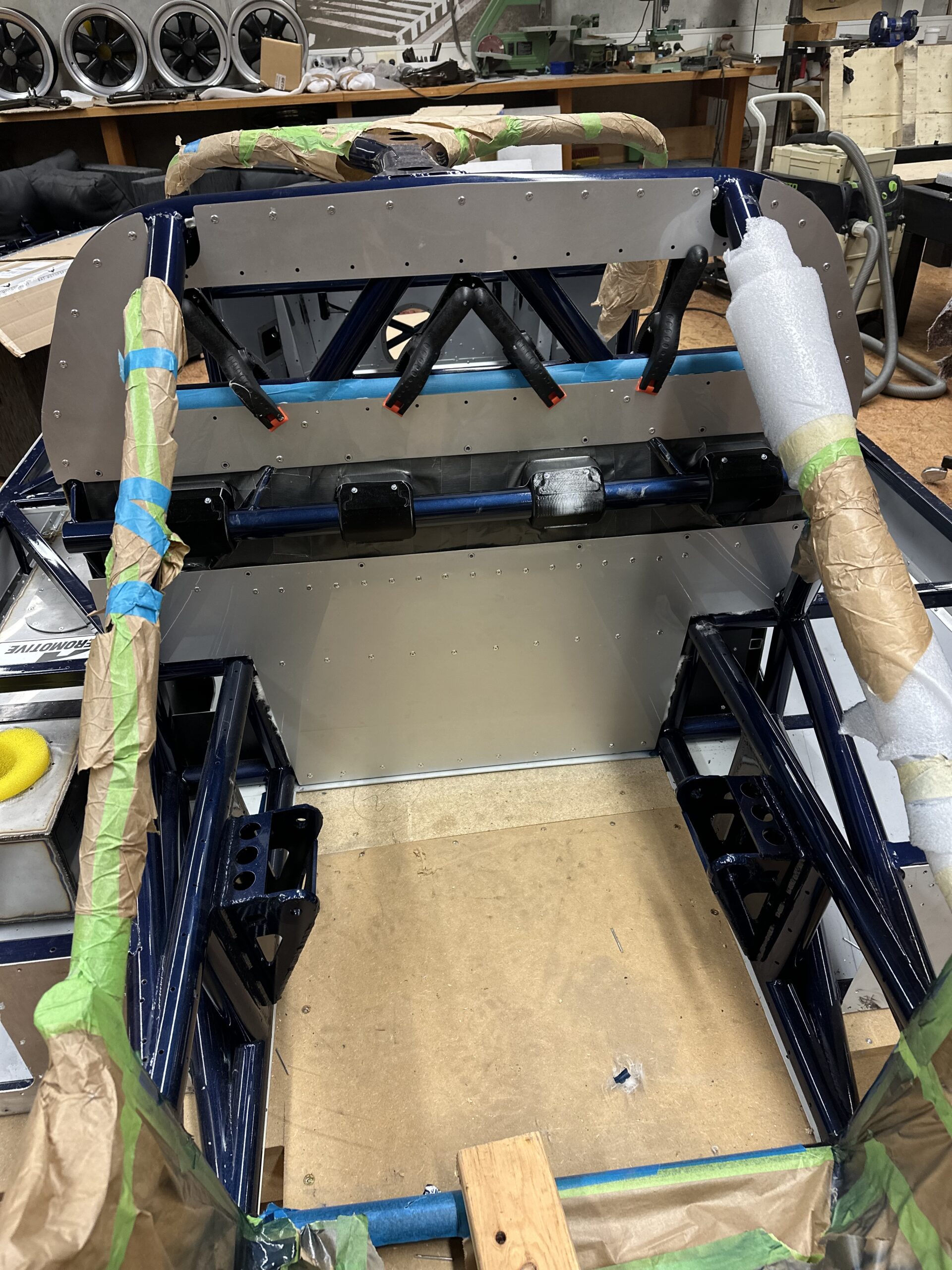
The shoulder straps are attached using loops that are placed around the belt tube. There are clear specifications and suitable accessories for this. As the belt tube is located in the engine compartment behind the firewall, I have provided the areas for the belt loops with 3D-printed covers. These protect the belts and can also be unscrewed to ensure accessibility for maintenance work. In addition, the pipe is covered by a metal sheet to further secure it and shield it from noise and heat from the engine
The lap belts and leg straps share the same attachment points in the 6-point harness formula. This ensures that they cannot “dive through” under the lap belt. I created the attachment points using specially welded brackets on the frame. Here too, exact compliance with the specifications was crucial.
This issue took an enormous amount of time and thought. It was impossible to determine the optimum position for the belts without extensive trial fitting. It shows again that a well thought-out plan and early integration of the belts into the frame construction would have been crucial. But in the end, I am happy with the current solution and hope that it will prove its worth on the first test ride.
And once again – you’re always smarter afterwards….

Leave a Reply
You must be logged in to post a comment.