Fuel supply: Tanks and safety


Safety aspects of fuel supply
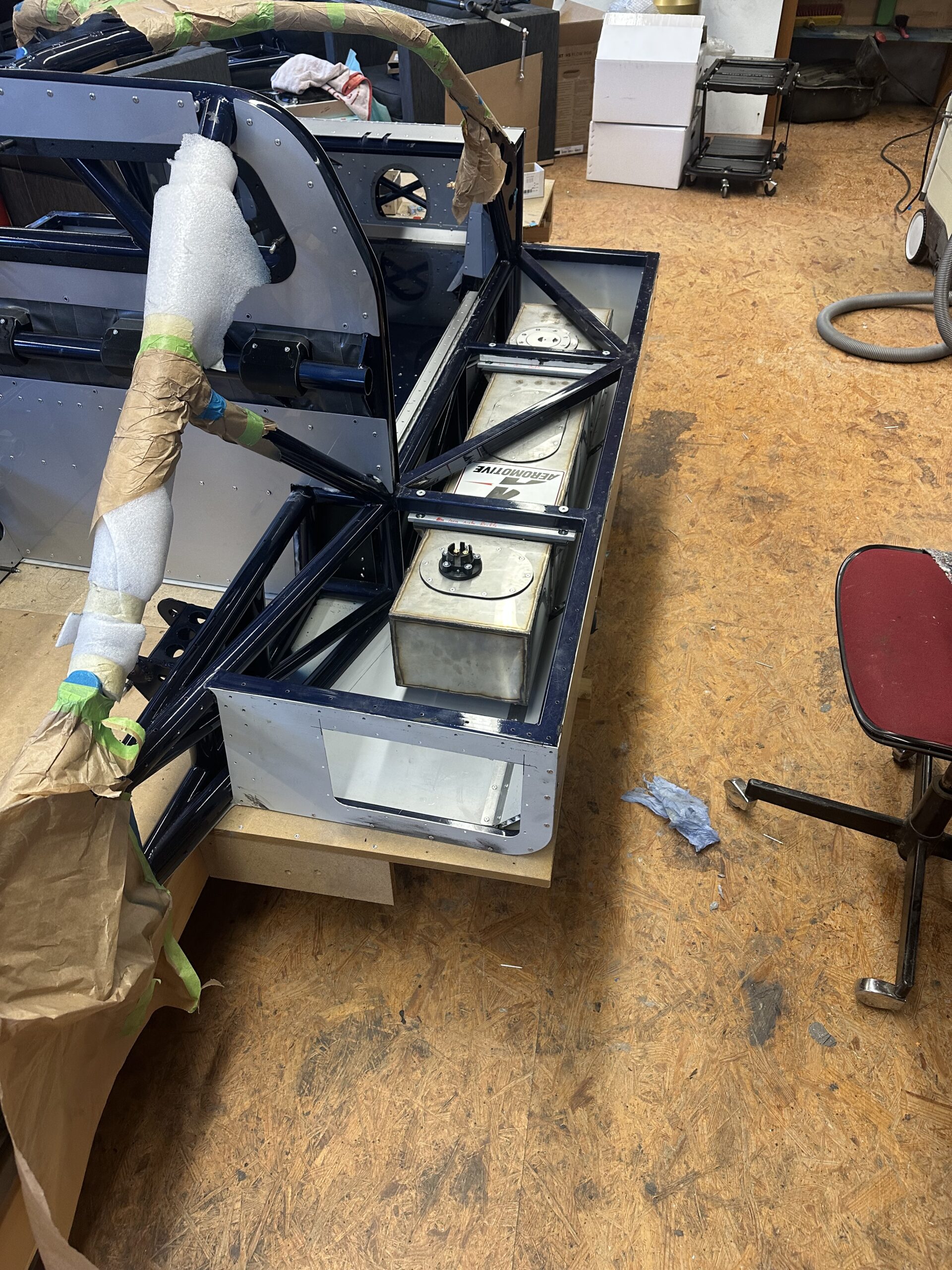
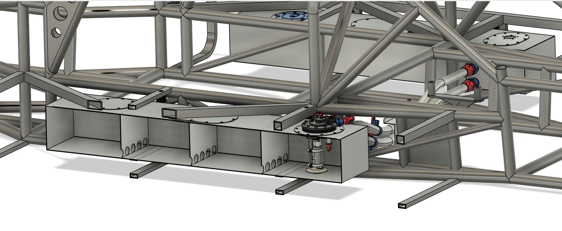
In the GT40, the position of the tanks is determined by the original design—they are located in the voluminous side skirts. Since I don’t need this area in my design to stabilize the frame, as is the case with the original, I had a little more creative freedom here.
There are also differences from the original in terms of the amount of fuel required: while the GT40 was equipped with the largest possible fuel tanks for 24-hour races, a capacity sufficient for about an hour of racing is enough for me.
Of course, at the beginning, I thought long and hard about using special safety tanks, known as fuel cells, such as those offered by ATL. However, finding suitable long and flat models proved extremely difficult. Most prefabricated tanks were either too tall or too wide to fit into the sills. Although it is possible to have such tanks custom-made, the price per unit is at least €2,000 – often even higher.
Another aspect that spoke against the immediate use of fuel cells was their limited service life: these tanks are usually only approved for five years, as the inner rubber cell has to be replaced regularly. For me, this meant that the approval might have expired before my car was ready for use.
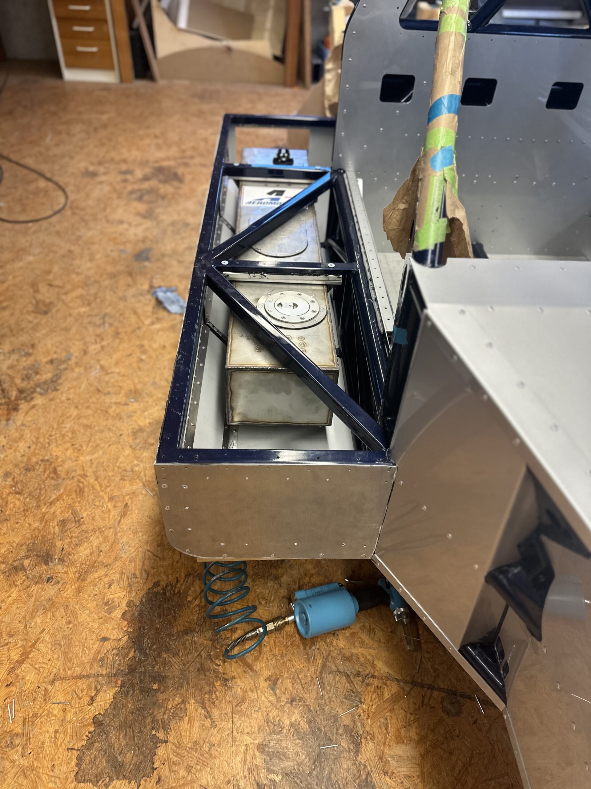
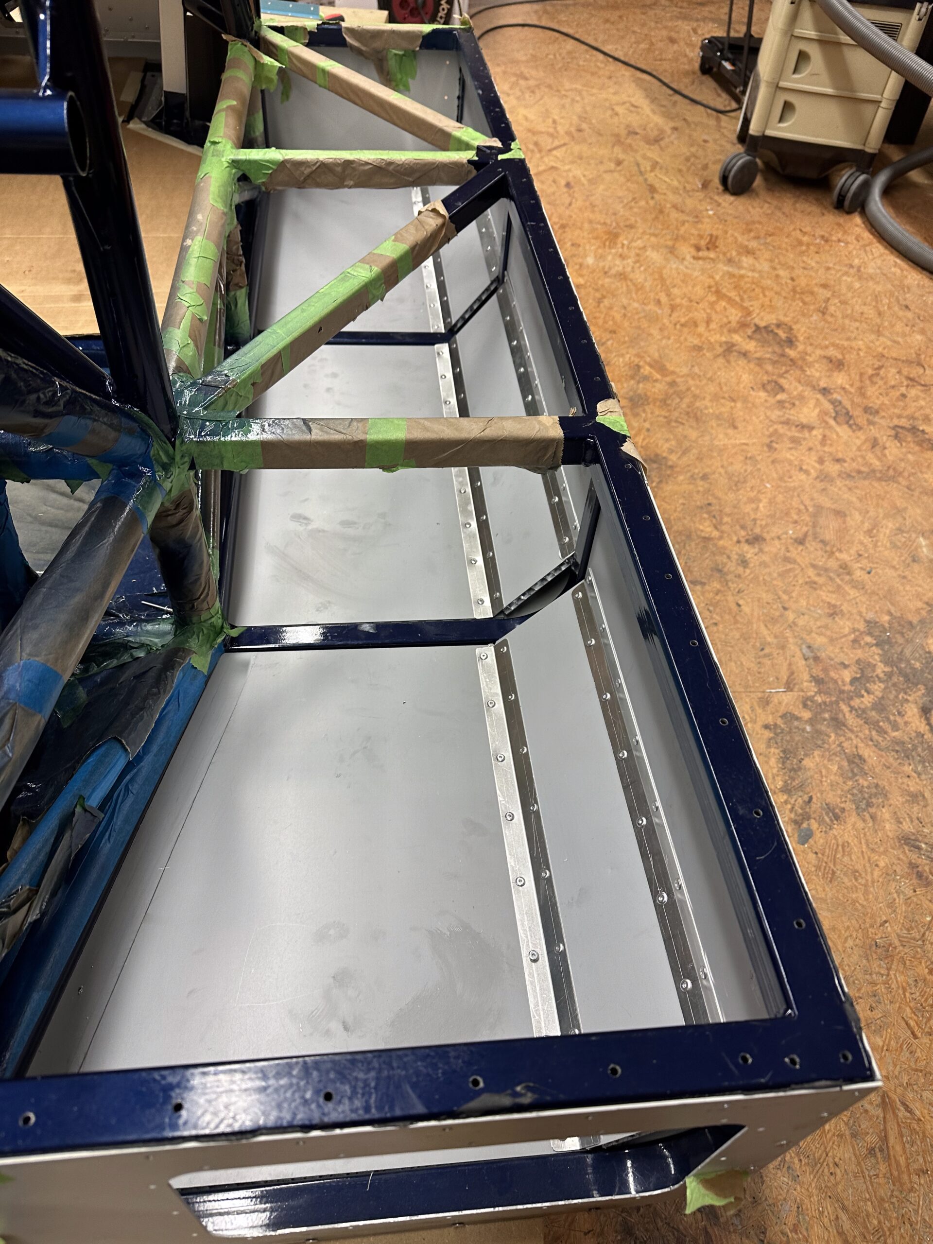
So I decided on a compromise: I designed tanks made of 1 mm thick stainless steel sheet. These are equipped with baffles to stabilize the fuel when cornering. I also integrated maintenance hatches so that the tanks can be filled with tank foam after welding.
To further increase protection, each tank is attached to a surrounding, welded stainless steel band. This bracket is screwed to the most solid part of the side boxes, the top, with four M8 screws each. I deliberately left as much space as possible between the brackets and the outside of the sills to gain additional space and protection.
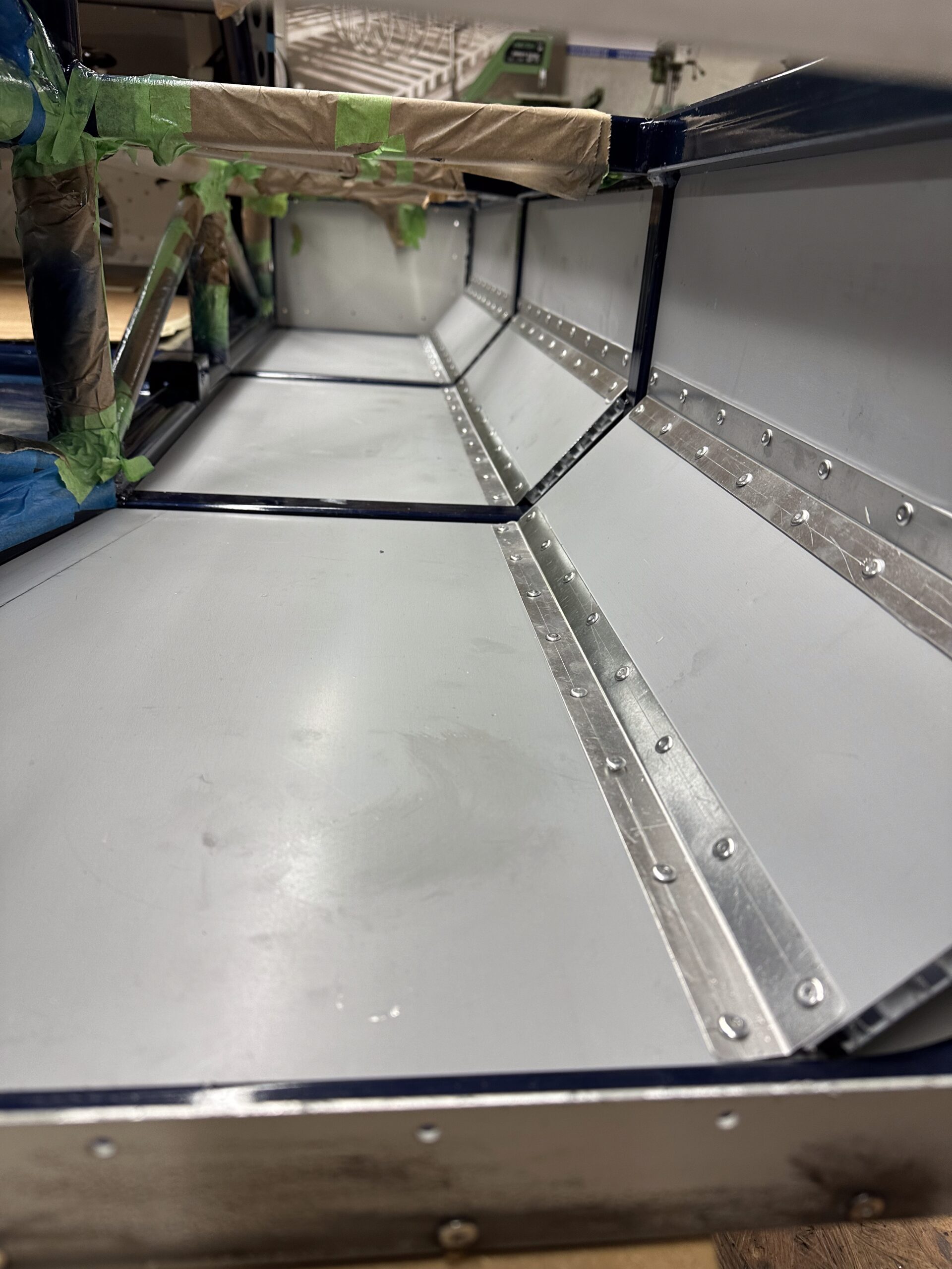
I reinforced the inside of the aluminum cladding on the sills between the solid, curved steel beams with 10 mm thick aluminum honeycomb sandwich panels. These panels are glued flat and supported by a 45° angle piece that reinforces the transition from the floor panel to the side wall. This construction serves purely as a crash structure and is designed to absorb energy in the event of an impact.
Of course, there is still a residual risk—that’s the price you pay when you rebuild a race car from the 1960s. Back then, people were much more willing to accept risks than they are today, and as we all know, enough went wrong.
Construction of fuel tanks
For the fuel tanks, I deliberately chose 1 mm thick stainless steel sheet, as I was advised against using aluminum due to modern types of gasoline. Aluminum tends to corrode when used with today’s fuels, which I wanted to avoid at all costs. The tanks each measure 1155 x 220 mm with a height of 156 mm.
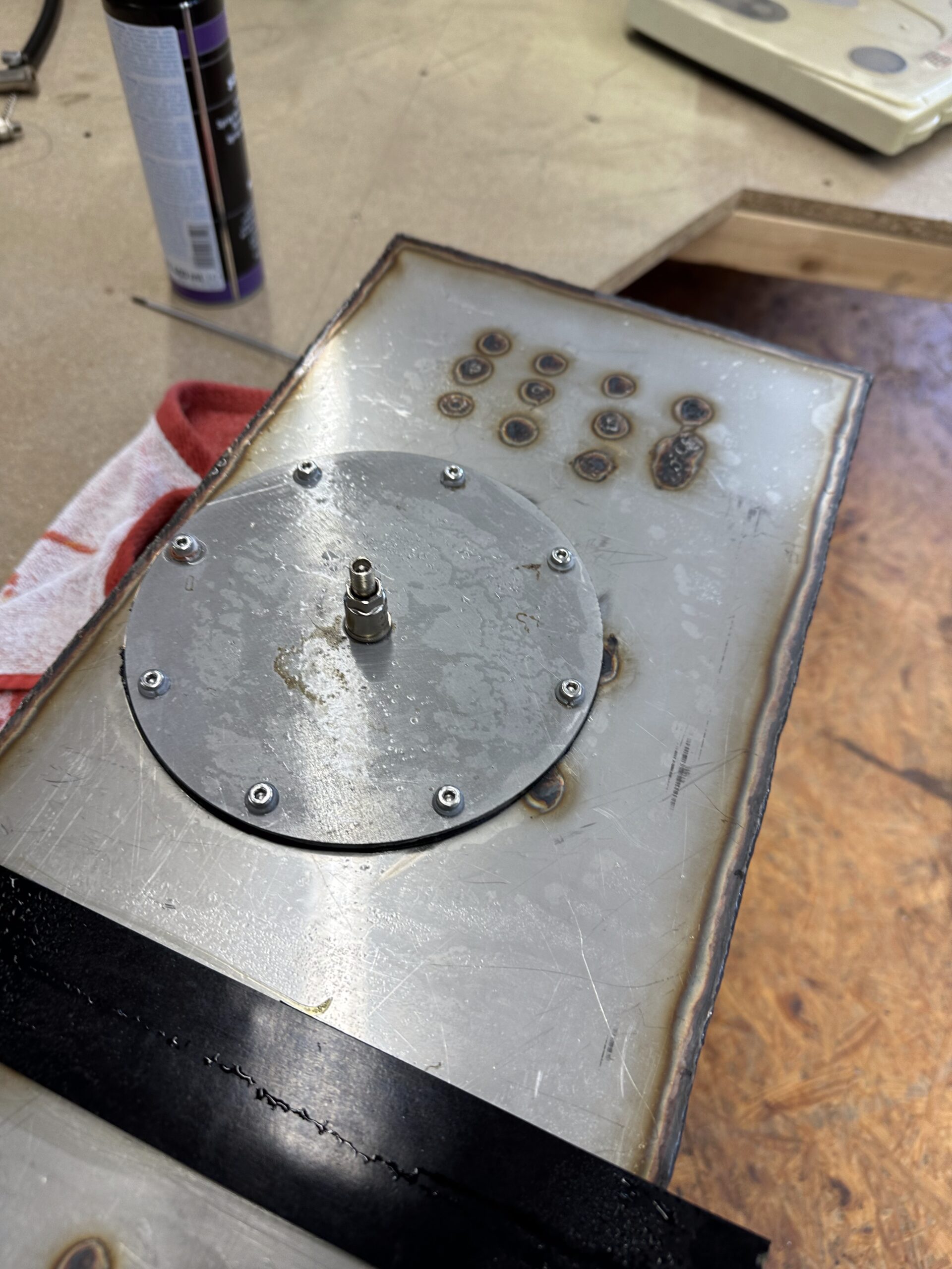
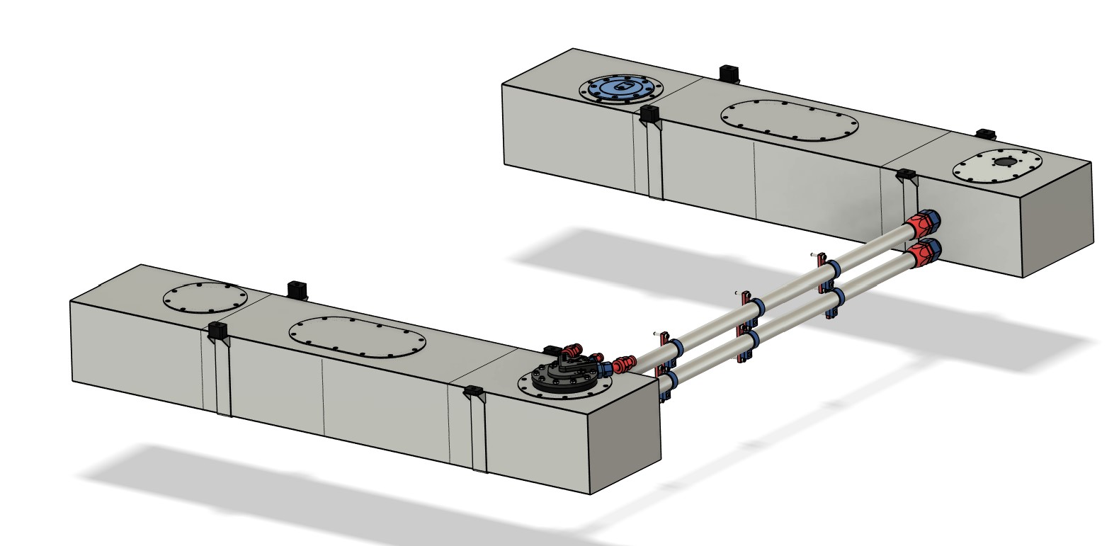
Inside the tanks are three baffles that do not reach the top and have five 30 mm holes each at the bottom of the tank. This design divides the tank into four chambers that stabilize the fuel during rapid changes of direction. To fill the tanks with tank foam, I attached three removable lids to the top. These are large enough that you can easily reach into the chambers with your hand.
The tanks are secured using two welded stainless steel straps per tank, which are additionally stabilized by brackets. Four M8 rivet nuts per tank enable secure yet removable fastening.
To connect the two tanks, I used two Dash 16 lines that run along the engine compartment side of the fire wall. In the original design, an 80 mm pipe was used for this purpose, which ran under the backrest in the passenger compartment—an unacceptable safety risk in my opinion. Splitting the line into two smaller lines was necessary for space reasons, but it also provides significantly greater safety.
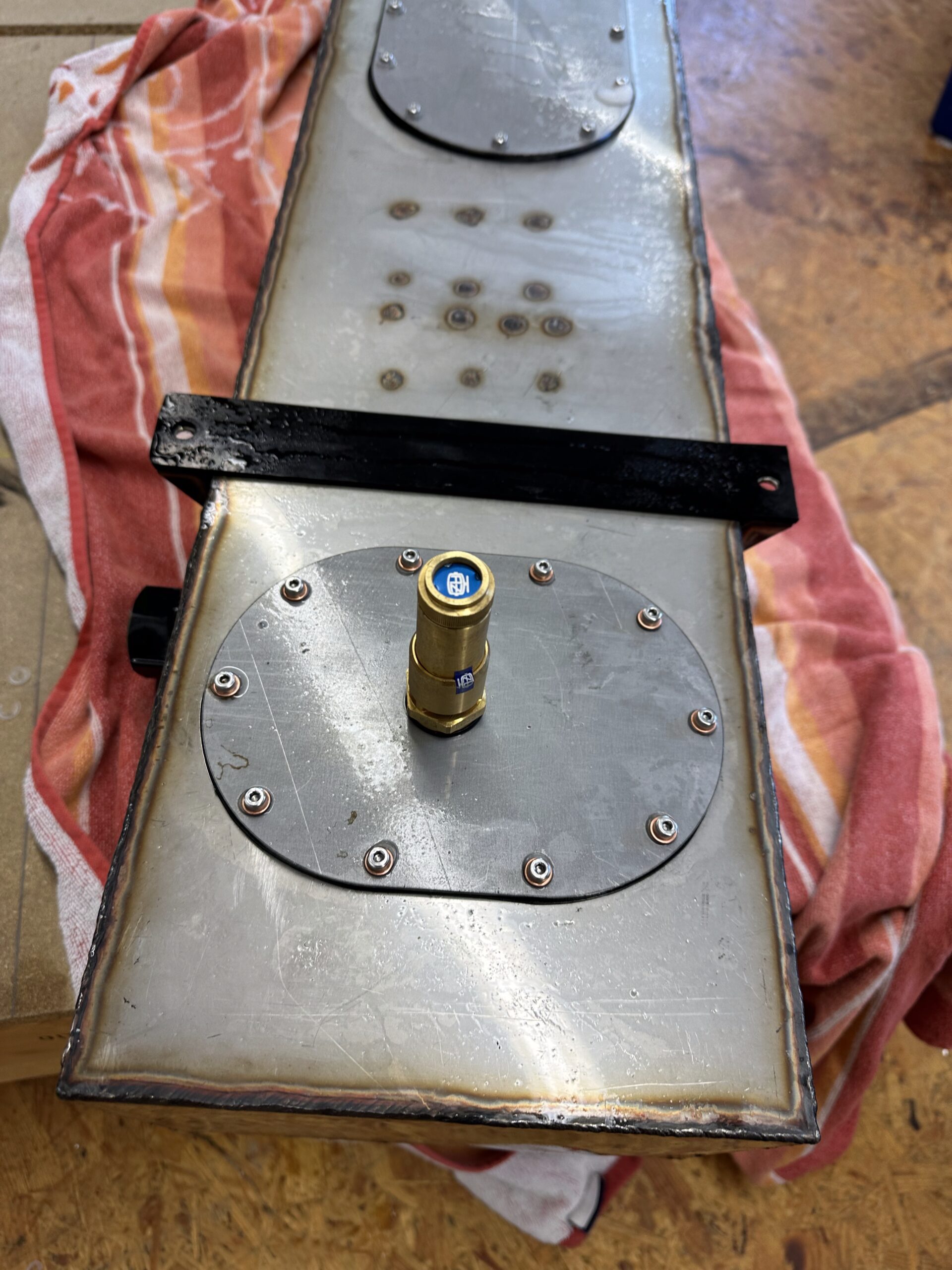
Both tanks have their own fuel caps, which are mounted directly on the tanks. I don’t need a quick-fill device, so refueling is done separately on the left and right. The left tank contains the sensor for the fuel gauge, while the right tank houses the internal fuel pump.
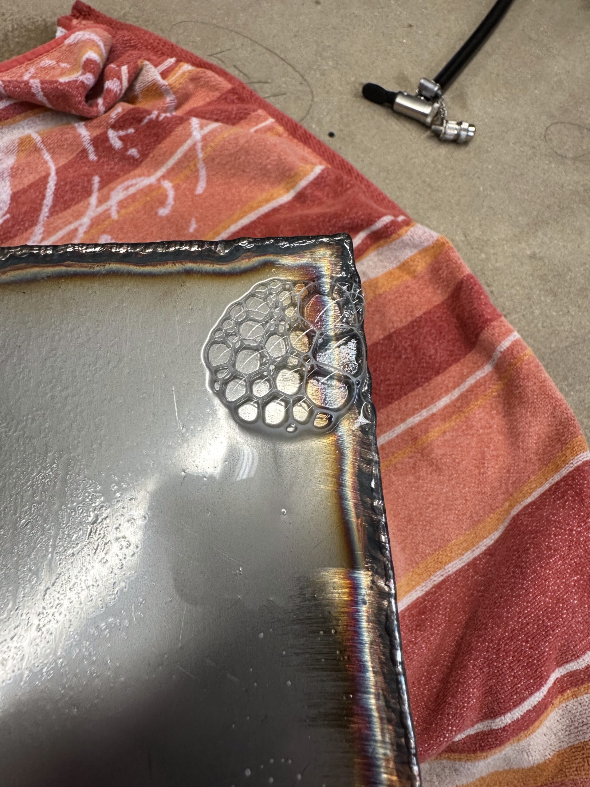
After welding and before filling with safety foam, I filled the tanks with 0.6 bar pressure and carefully checked them for leaks using leak detection spray. Special care must be taken here: 0.6 bar may seem low at first glance, but the pressure acts evenly on the entire inside of the tanks and generates considerable forces. In fact, I noticed a slight “bulge” during this step.
To ensure that the pressure does not rise too high, I have installed a special cover on the access holes with an automatic pressure valve from the heating industry. This valve blows off precisely at 0.6 bar, providing additional safety during testing.
Pump system and pipes
The topic of fuel pump systems alone could fill entire books—or at least extensive discussions such as those on the GT40s.com forum. The relevant posts there examine all conceivable possibilities and aspects in detail. If you would like to take a closer look, you can find the posts here.
In this section, I would like to limit myself to my personal approach. As with the cooling system, I wanted the simplest possible design; I can always change it later if I deem it necessary.
Therefore, I have decided to use a single fuel pump for the time being.
My engine is powered by a classic Holley carburetor—for reasons of originality, appearance, cost, and, last but not least, its characteristic sound. After the break-in period and initial test drives, I could switch to a fuel injection system such as the Holley Sniper System, but programming fuel injection seemed too complicated for me to start with.
When redesigning a race car, you should always make sure to keep the design as simple as possible at the beginning. Even in a simple system, there are still plenty of potential sources of error. Individual areas can be easily optimized later on once the vehicle is running reliably.
The decision to use a carburetor has one key advantage: I can operate the tanks without pressure. This simplifies both ventilation and eliminates the need for a return circuit. I use the Phantom 200 Stealth Fuel System from Aeromotive as the pump, supplemented by the appropriate dash adapters, filters, pressure regulators, and other accessories. You can find the connection diagram I used in the image gallery below.
The lines used consist of high-quality hoses encased in steel braiding. These not only offer high pressure resistance, but are also extremely heat-resistant—a standard that should be a given in racing cars.
With this setup, I will try to get the car up and running reliably. As already mentioned, changes and optimizations remain possible at any time. After all, it is only during operation that it becomes clear where fine-tuning is necessary. We’ll see…
Leave a Reply
You must be logged in to post a comment.