Fuel supply: Tanks and safety

Safety aspects of the fuel supply

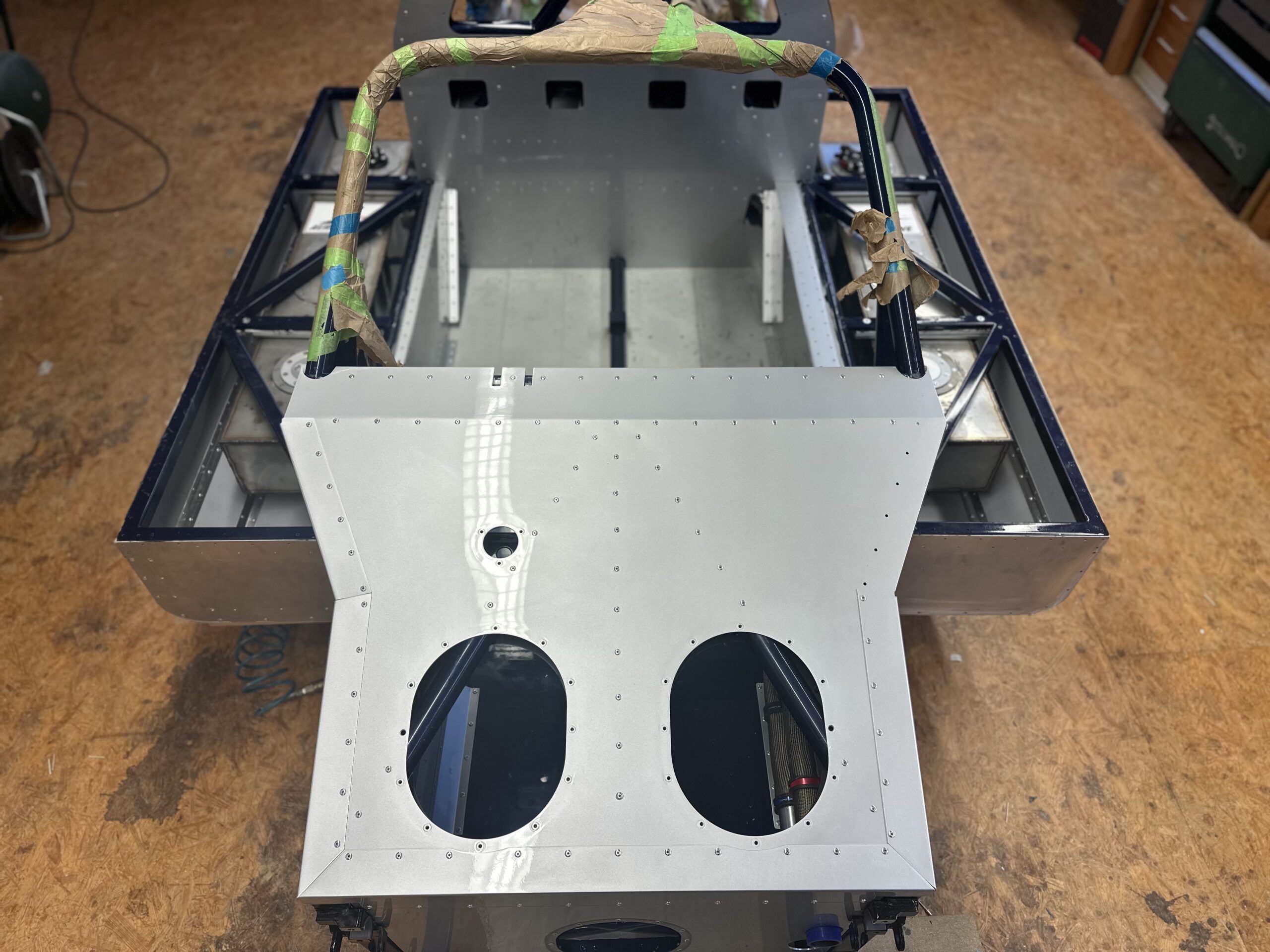
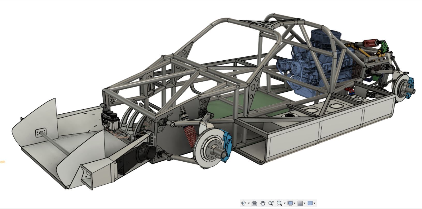
On the GT40, the position of the tanks is predetermined by the original design – they are located in the voluminous side sills. As I don’t need this area in my design to stabilize the frame as in the original, I had a little more creative freedom here.

There are also differences to the original in terms of the amount of fuel required: While the GT40 was equipped with the largest possible fuel tanks for 24-hour races, I only need a capacity that is sufficient for about one hour of racing.

Of course, at the beginning I thought long and hard about using special safety tanks, so-called fuel cells, such as those offered by ATL. However, the search for suitable, long and flat models proved to be extremely difficult. Most of the prefabricated tanks were either too high or too wide to fit into the sills. Although it is possible to have such tanks custom-made, the price per piece is at least 2,000 euros – often even higher.

Another aspect that spoke against the immediate use of fuel cells was their limited service life: these tanks are usually only approved for five years, as the internal rubber cell has to be replaced regularly. For me, this meant that the approval might have expired before my car was ready for use.

I therefore decided on a compromise: I constructed tanks from 1 mm thick stainless steel sheet. These are fitted with baffle plates to stabilize the fuel when cornering. I also integrated maintenance hatches so that I could fill the tanks with tank foam after welding.

To further increase protection, each tank is attached to a circumferential, welded stainless steel band. This bracket is bolted to the most solid part of the side boxes, the top, with four M8 bolts each. I deliberately left as much distance as possible to the outside of the sills to provide additional clearance and protection.

I also braced the inside of the aluminum cladding of the sills between the solid, curved steel beams with 10 mm thick aluminum honeycomb sandwich panels. These panels are glued flat and supported with a 45° angle piece that reinforces the transition from the floor panel to the side wall. This construction serves purely as a crash structure and is designed to absorb energy in the event of an impact.

Of course, there is still a residual risk – that’s the price you pay when you recreate a racing car from the 1960s. Back then, the acceptance of risk was much higher than it is today, and as we all know, enough things have gone wrong

Construction of the fuel tanks

For the fuel tanks, I deliberately opted for 1 mm thick stainless steel sheet, as I was advised against using aluminum due to modern types of fuel. Aluminum tends to corrode in combination with today’s fuels, which I wanted to avoid at all costs. The tanks each measure 1155 x 220 mm with a height of 156 mm.

Inside the tanks there are three baffle plates that do not extend to the top and are each provided with five 30 mm holes at the bottom of the tank. This construction divides the tank into four chambers, which calm the fuel during rapid changes of direction. In order to be able to fill the tanks with tank foam, I attached three unscrewable lids to the top. These are large enough so that you can easily reach into the chambers by hand.

The tanks are attached using two welded stainless steel straps per tank, which are additionally stabilized by brackets. Four M8 rivet nuts per tank enable secure yet detachable fastening.

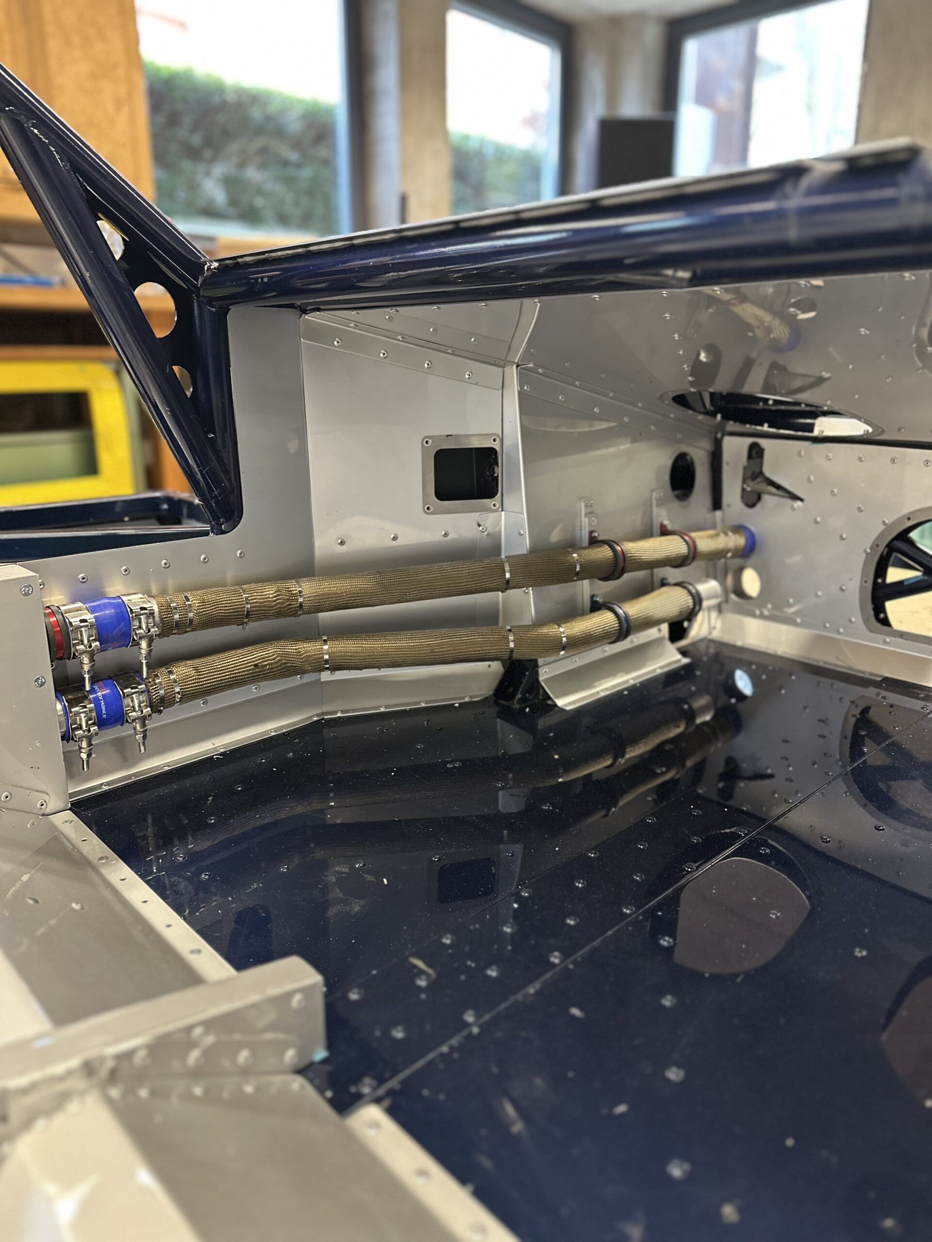
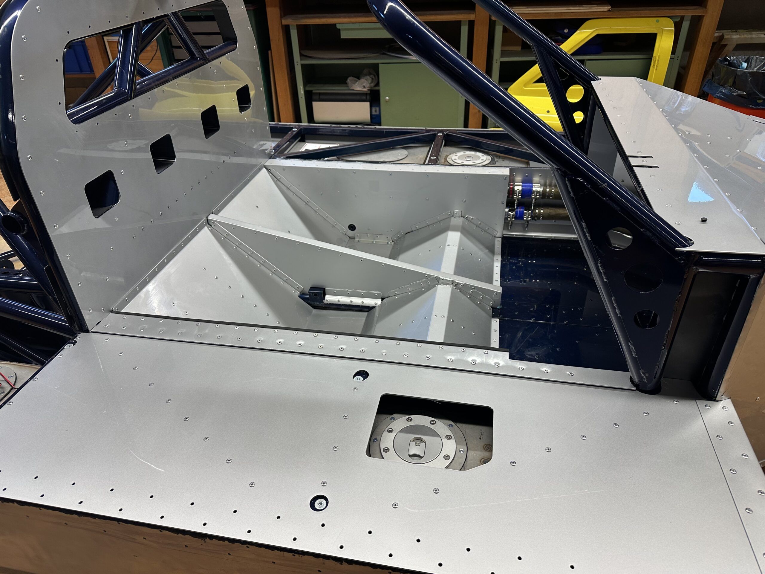
To connect the two tanks, I used two Dash 16 lines that run on the engine compartment side of the firewall. In the original, an 80 mm pipe was used for this, which ran under the backrest in the passenger compartment – an unacceptable safety risk for me. The division into two smaller pipes was necessary for reasons of space, but provides significantly more safety.

Both tanks have their own fuel caps, which are mounted directly on the tanks. I don’t need a quick refueling device, so the left and right tanks are refueled separately. The left tank contains the sensor for the fuel gauge, while the right tank houses the internal fuel pump.

After welding and before filling with safety foam, I filled the tanks with 0.6 bar pressure and carefully checked for leaks with leak detection spray. Special care is required here: 0.6 bar may seem low at first glance, but the pressure acts evenly on the entire inside of the tanks and generates considerable forces. In fact, I noticed a slight “bulge” during this step.

To ensure that the pressure does not rise too high, I have fitted an automatic pressure valve from the heating industry on a special cover for the access holes. This valve blows off precisely at 0.6 bar and thus provides additional safety during the test.

Pump system and lines

The subject of fuel pump systems alone could fill entire books – or at least detailed discussions such as those in the GT40s.com forum. Corresponding articles there illuminate all conceivable possibilities and aspects in detail. If you would like to take a closer look, you can find the articles here.

I would like to limit myself to my personal approach in this section. As with the cooling system, I wanted the design to be as simple as possible, but I can always change this later if I feel it is necessary.
That’s why I decided to go for a single fuel pump for the time being.

My engine is supplied by a classic Holley carburetor – for reasons of originality, appearance, cost and not least because of the characteristic sound. After the running-in phase and initial test drives, I could switch to a fuel injection system such as the Holley Sniper system, for example, but programming a fuel injection system seemed too complex for me to begin with.

When designing a new racing car, you should always make sure to keep the setup as simple as possible at the beginning. Even in a simple system, there are still plenty of potential sources of error. Individual areas can easily be optimized later as soon as the vehicle is running reliably

The decision to use a carburetor has a decisive advantage: I can operate the tanks without pressure. This simplifies both the ventilation and the elimination of a return circuit. The pump I use is the Phantom 200 Stealth Fuel System from Aeromotivesupplemented by the appropriate dash adapter, filter, pressure regulator and other accessories. You can find the connection diagram I used in the picture gallery below.

The lines used consist of high-quality, steel braided hoses. These not only offer high pressure resistance, but are also extremely heat-resistant – a standard that should be a matter of course for racing vehicles.

With this setup, I will try to get the car running reliably. As already mentioned: changes and optimizations are always possible. After all, it will only become clear where fine-tuning is needed when the car is in operation. We’ll see…


The cooling system of the GT40 MKIV: challenges and solutions

Planning and designing the cooling system for my Ford GT40 MKIV was one of the more complex tasks I faced. The limited space in the engine compartment, the requirements of a powerful V8 mid-engine and the desire to preserve the original appearance of the vehicle posed particular challenges.

Positioning the coolers and pipes

A major problem in the design of the cooling system was the extremely small engine compartment. A conventional mechanical water pump simply wouldn’t fit. After intensive research, I decided to switch to an electric water pump. The forum recommended two manufacturers who offer pumps for high-displacement engines: Pierburg (Germany) and Davies Craig (Australia).

Both manufacturers kindly provided me with CAD data, which helped me with the planning. I would have liked to use the Pierburg pump, but it could not be integrated into the overall system in a flow-optimized way. In the end, my choice fell on the Davies Craig EWP150the manufacturer’s most powerful pump, which is often used in conjunction with US engines. The technical support from Davies Craig was particularly helpful and provided me with significant assistance in designing the cooling system.

However, the pump alone was not enough. The EWP150 requires a programmable controller and suitable accessories for integration into the cooling system. Davies Craig offers complete installation kits that can be obtained from various dealers in Germany or directly from Australia. Another advantage of this solution is the ability to control the cooling system efficiently and individually.

An additional component is the connection to the engine.
As I couldn’t install an original water pump, I had to design my own cover, which is installed instead of the normal water pump and creates the hose connection to the pipes for the electric water pump. This was also a CNC milled part, which I redesigned several times to reduce the milling costs.

Challenges in the design of the cooling system

There were many decisions to be made when designing the cooling system:

  • Diameter of the cooling water pipes: These must be dimensioned in such a way that they ensure a sufficient flow rate without taking up too much space. I opted for 38 mm, with a wall thickness of 2 mm, all made of aluminum.
  • Choice of material: Durability and low weight were decisive factors in the choice of aluminum tubes.
  • Integration of a heater: In the end, I decided not to install a heater, as this is a pure racing car. Instead, I plan to install an electrically heated fan to ventilate the windshield. However, I haven’t thought about this in detail yet.
  • Positioning the water pump: There are two different opinions on this: Some experts recommend positioning the pump as close to the radiator as possible, while others advocate placing it as close to the engine as possible. This discussion is particularly relevant for vehicles with a mid-engine, as the distance from the radiator to the engine is almost three meters. After consulting with both pump manufacturers, I decided to follow the recommendation to mount the pump as close to the radiator as possible. The reasoning: The suction power of the pump is weaker than the pressure power, which is why the suction path should be kept as short as possible. As I am not an expert in this field myself, I followed the manufacturer’s recommendation.
  • Connecting pieces and hoses: There are several transfer points and changes of direction in the cooling circuit. First of all, I determined the available silicone hose elbows, so what are the standard angles. I use straight silicone hoses from Viper-Performance, obtained from BAT-Motorsport, as well as bends at 30°, 60° and 90°. I then used these in CAD along the projected path of the radiator lines and then constructed the necessary short connections from straight and bent pipe sections. In this way, I was able to dispense with complex special hoses. Motorsport double hose clamps round off the whole thing.

My philosophy was clear: as simple as possible, as effective as necessary. A minimalist system is less prone to problems and remains easy to maintain.

The characteristic radiator line of the GT40 MKIV

Another special feature of all GT40 models are the long cooling water pipes that run from the engine compartment to the front radiator. In the GT40 MKIV, they run along the left-hand interior side wall and are a striking feature of the design. I really wanted to preserve this iconic look.

As the pipes have several bends, I split them so that they could be dismantled if problems arose. For this reason, the panels of the passenger seat had to be designed to be screwable so that the pipes could still be accessed in the finished car. The majority of the pipes run inside the side wall of the passenger seat, which resulted in a complicated construction of the seat. This meant that the space available towards the rear of the engine compartment was extremely tight.

It was also a challenge to find an affordable manufacturer for the pipes and the radiator who could produce such complex parts. I found what I was looking for in England at Concept Racing. The designer there, Clare, was super nice and helpful. I sent them precise 2D drawings and 3D models and received parts that fit perfectly. However, one tube required a short video that I created in CAD to show how it needed to be bent and welded. This 10-second movie avoided tedious mistakes – cheers to the possibilities in Fusion 360!

The choice of cooler

I also relied on Concept Racing’s expertise when selecting the radiator. The length and width of the radiator had to make optimum use of the limited space in the vehicle without compromising efficiency. The thickness of the radiator also played a decisive role. While the original radiator was almost 100 mm thick, modern high-performance grilles today allow a comparable cooling performance with significantly smaller dimensions. That’s why I opted for a thickness of 60 mm, which both saves weight and improves airflow.

The design details such as the position of the connections, the attachment of the radiator, threads for the temperature sensors of the electric water pump, etc. were precisely coordinated.
The design of the air baffles to the radiator was also difficult, as one part is fixed to the frame and the other part is attached to the hinged hood. Here, too, I had to try out several design variants in order to hopefully achieve a good end result.

Conclusion ?

I can’t really come to any conclusions on this subject at the moment, firstly because I haven’t yet bought all the parts, such as the water pump, and secondly because the parts I already have haven’t all been installed yet.
I’ll report later on whether I’ve done everything right….


Steering: precision and safety

Choosing the right steering system

Choosing the right steering system for my Ford GT40 MKIV was one of those decisions where precision and safety were once again paramount.
When designing the frame, it quickly became clear that the original, unchanged track width on the front axle in conjunction with the wide rims would lead to very short wishbones and track rods. This generates high steering forces, especially when using modern tires. Servo assistance was therefore indispensable – especially for a car that puts over 500 hp on the road.

I naturally opted for a power steering system from the racing world. This solution combines the best of both worlds: the direct and precise control I want with the necessary support to move the car safely and comfortably. After a lot of research and a few discussions with experts from racing teams, I chose the Woodward Precision Power Steering System.

Why Woodward?

  1. A flexible modular system: I am not aware of any other supplier that really offers such extensively customizable power steering systems for such projects.
    Woodward convinced me with their modular approach, which allowed me to customize the steering to the exact requirements of my car. This flexibility was the decisive point for me.
  2. Racing quality: Woodward stands for racing. Their products are not only developed for everyday use, but also for tough use on the race track. The fact that they were recently successful in the LMP2 class at Le Mans with the steering system I used shows how seriously they take their work – and that’s exactly what I wanted for my project.
  3. Perfect integration into the CAD model: A big plus point was that Woodward was the only company willing to provide me with a STEP file of their system. This file helped me immensely to integrate the steering system seamlessly into my CAD model and ensure that it fits perfectly.

I only had to fill out a data sheet with a few details, received the corresponding CAD file after 3 days and after only 3 weeks from the USA I have the steering system here in my workshop.

Choosing Woodward not only made technical sense, but also gave me the feeling that I had taken another important step towards my dream. I am always impressed by how much engineering skill goes into a system like this. I am sure that it will make a decisive contribution to making my GT40 MKIV a vehicle that not only looks like a racing car, but also feels like one.

Tuning the steering to the chassis geometry

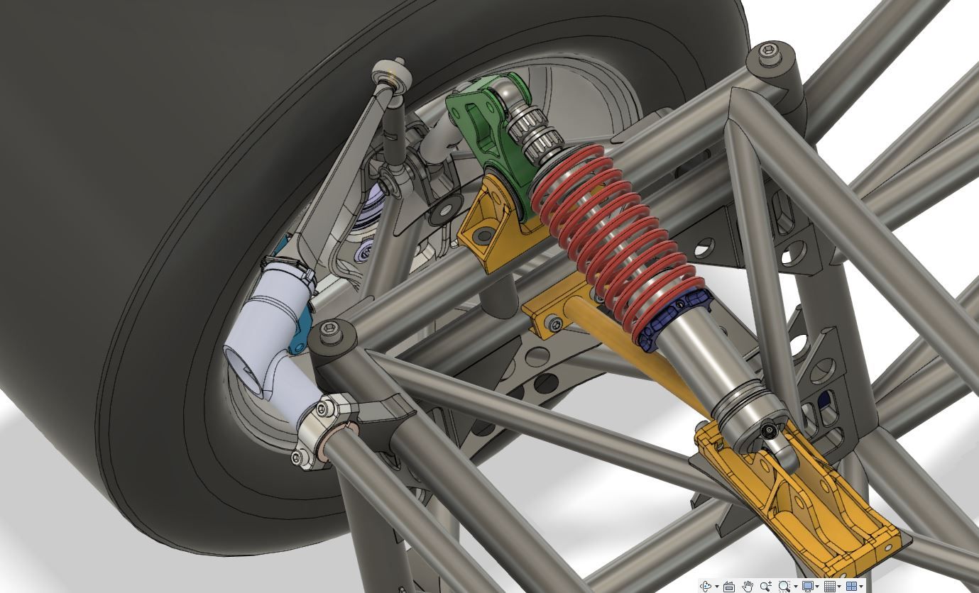
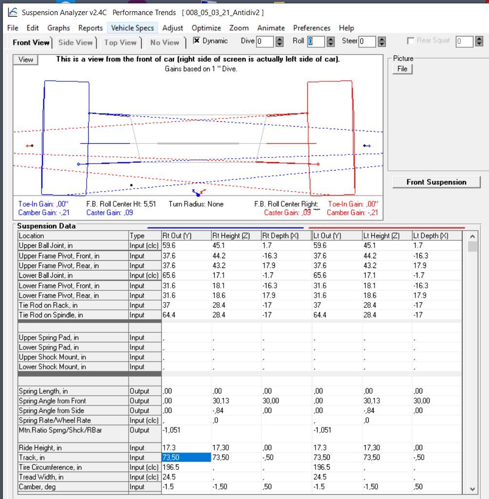
Matching the steering to the chassis geometry is an extremely complex task. It’s not just about correctly calculating the Ackermann angle – the different steering geometry of the front wheels in a bend. Modern suspension designs take far more into account: for example, the steering angle of the front wheels changes during compression and rebound, ideally in such a way that the driving characteristics are improved.
Unwanted steering movements due to compression or rebound – the famous “bump steering” – must be avoided at all costs, as it significantly impairs cornering behavior and therefore driving safety.

These dynamic kinematics considerations are a field of their own that could be the subject of entire books – and that would go beyond the scope of this article. I must honestly admit that I couldn’t manage this task on my own. Fortunately, I was able to count on the support of my friend Uwe Bleck (kinematic engineer) for the steering geometry, who helped me considerably with his knowledge and experience. Finding the correct pivot points in space and designing the geometry in such a way that it fulfills both the historical charm and the requirements of a modern, high-performance vehicle was an enormous challenge.
It was already complicated enough for me to design the necessary pivot points on the wheel and frame.

Of course, the rear axle should not be forgotten, as the wheel is also held at the correct angle by a tie rod. With the correct arrangement of the mounting points, it is even possible to achieve that the rear wheels “steer” slightly when deflecting and thus further improve the riding characteristics.

The whole issue of suspension and steering is simply overwhelming. With over 25 degrees of freedom, you can quickly become dizzy. During the coronavirus pandemic, I spent months familiarizing myself with the system and now I just understand the basics. Even if you theoretically grasp everything, you simply don’t have the many thousands of hours of test work on the racetrack. I am convinced that only experts can solve this complex puzzle.

Without the help of my two friends Uwe Bleck and Andy Köhler, who don’t know each other, this would have been impossible for me. And if they did know each other, they would probably have endless discussions about which is better – and it often remains unclear who is actually right! 😊


Seat position and pedals: ergonomics and functionality

The correct seating position in a vehicle like the Ford GT40 MKIV is far more than just a question of comfort – it is crucial for control, safety and driving experience. In this article, I would like to discuss the challenges and considerations that played a role in the design of the seat position, pedals and their integration into the overall structure.

1. determination of the optimum seating position in CAD

As mentioned in the first post, I made a fundamental mistake at the start of the project: instead of first determining the seating position and designing the frame around it, I went the other way round. As a result, I was later forced to make compromises that are still with me today.

One example is the tapering of the frame at the front right, which obstructs my right leg. In addition, I should have positioned the longitudinal tube in the middle of the vehicle floor slightly off-center to allow a more central seating position. Instead, I am now sitting at a slight angle to the direction of travel – a minimal, but nonetheless annoying deviation.

After a long search, I was finally able to find a suitable CAD dummy that helped me to determine the seat position. This dummy enabled me to simulate the driver’s position in CAD and draw initial conclusions about the room layout. On this basis, I designed and built two different wooden seats to test the theoretical planning in practice. The tests showed that it is hardly possible to determine an ideal seating position using CAD alone. You have to test the position in reality – especially to find the compromise between the lowest possible seating position for headroom and sufficient visibility over the dashboard.

I had already provided for additional headroom in the event of a side impact when designing the frame by moving the top of the middle section slightly to the left. This allows my head to slide under this structure in the event of an accident, which could prevent potentially serious injuries.

The original vehicle had a one-piece seat shell made of GRP that covered both seats. However, due to the Le Mans regulations, the passenger seat was only a narrow emergency seat in which hardly anyone could sit comfortably. As the production of such a GRP seat shell with mold construction etc. is very cost-intensive, I decided on a different solution: seat shells made of sheet aluminum. This method was also used in other racing cars at the time.

The comfort remains very low with both variants, but that is of secondary importance in a racing car anyway. After foaming the seat shells(here is an example of what this is), adapted to my body shape, I will cover them with black leather – just like the original. Visually, there will be no noticeable difference to the historic GRP seats.

A note for rebuilders: There are GRP seat shells for the Lola T70, which in my opinion are almost identical and could probably fit in the GT40 MKIV. However, I have only found pictures of them and no source of supply or price information. Still, it might be worth looking for these seat shells – maybe someone else will have better luck sourcing them.

2. design of the pedals with a focus on ergonomics and adjustability

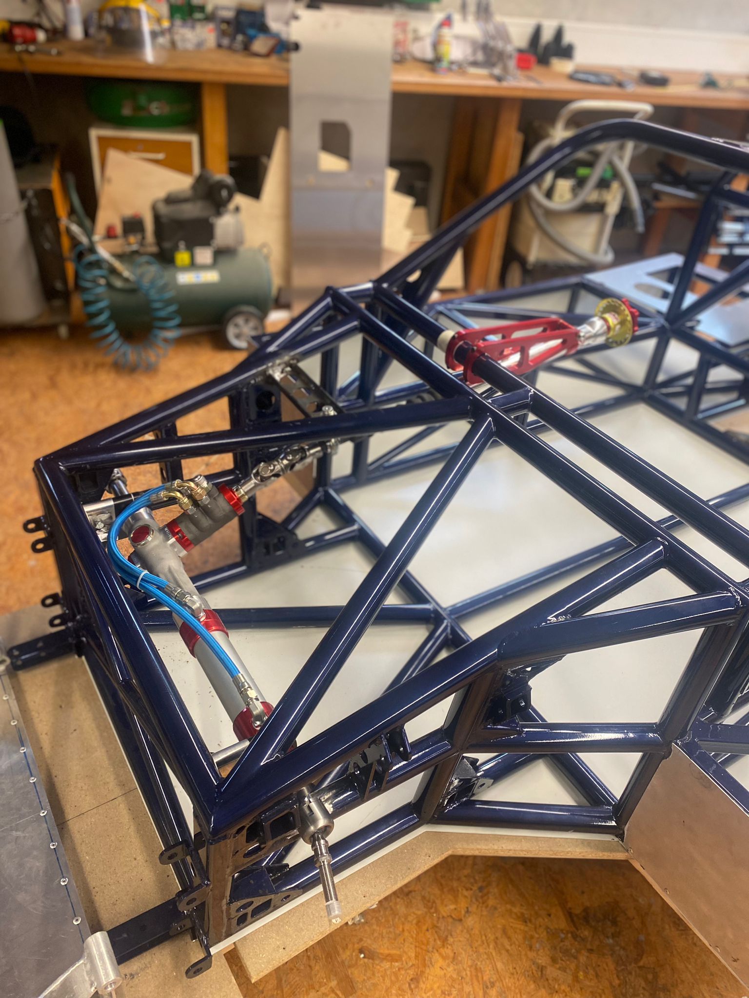
The construction of the pedals was one of the biggest challenges in the footwell of my GT40 MKIV. I extended the frame in the foot area by approx. 15 cm compared to the original – to create more foot space, to better attach the wishbones and the stabilizer bar and to accommodate the steering gear within the frame.

One important factor was the steering: the short levers of the front suspension generate high steering forces. I therefore decided to use a power steering system from racing. However, this solution presented its own challenges, as the steering gear is significantly larger than the original and had to be integrated in such a way that it did not restrict the freedom of movement for the feet.

The original vehicle had suspended pedals with an external cylinder unit. Due to my tubular frame, this design was not feasible for my vehicle. I therefore decided to make the pedals myself from aluminum. It was an intensive process, because space in the footwell is extremely limited – especially if you have size 45 shoes. Every millimeter decision had to be reconsidered to ensure that everything would really fit later on.

To create space for the tips of the shoes, I built a double joint into the steering column. This ensures that the steering column runs more efficiently without protruding directly into the range of movement of the pedals. I also opted for a pedal unit with the brake and clutch cylinders in front of the pedals – a solution that makes good use of the space, but also requires a lot of detail to get it just right.

To be honest, I don’t yet know whether this design will work in practice as I had imagined. The trial assembly will show whether everything harmonizes as I had planned, or whether I will have to fall back on commercially available pedals or even redesign them. In retrospect, I should probably have paid more attention to the integration of the steering gear, pedals and space requirements when planning. But that’s how it is sometimes with a project like this – you learn as you go and not everything works on the first try.

3. seat belts and their integration into the overall structure

The seat belts and their attachment points were a key aspect when designing the overall structure of my GT40 MKIV. Especially in a vehicle with such a low seating position, the correct attachment of the belts is crucial for safety and functionality.

For the planning, I intensively studied the specifications of the Schroth company, which provide very detailed information in the racing section. They define exactly which angles must be maintained for the individual belt parts, which minimum lengths are prescribed and how the attachment to the frame must be designed. These specifications are not only sensible, but also absolutely necessary to ensure safety in the vehicle.

Due to the seating position, I opted for 6-point harnesses from formula racing, which can be specially adjusted to suit your height. These belts provide the necessary safety and prevent you from slipping under the lap belt in the event of an accident.

A particular challenge was attaching the shoulder straps. In order to maintain the prescribed minimum distance of 90 mm to the shoulder and the correct angle range of 0° to -20°, I had to attach a special belt tube to the frame. This was a subsequent modification that became necessary because I had only designed the seat shell after the frame had been completed. This mistake caught up with me again and caused additional work.

The shoulder straps are attached using loops that are placed around the belt tube. There are clear specifications and suitable accessories for this. As the belt tube is located in the engine compartment behind the firewall, I have provided the areas for the belt loops with 3D-printed covers. These protect the belts and can also be unscrewed to ensure accessibility for maintenance work. In addition, the pipe is covered by a metal sheet to further secure it and shield it from noise and heat from the engine

The lap belts and leg straps share the same attachment points in the 6-point harness formula. This ensures that they cannot “dive through” under the lap belt. I created the attachment points using specially welded brackets on the frame. Here too, exact compliance with the specifications was crucial.

This issue took an enormous amount of time and thought. It was impossible to determine the optimum position for the belts without extensive trial fitting. It shows again that a well thought-out plan and early integration of the belts into the frame construction would have been crucial. But in the end, I am happy with the current solution and hope that it will prove its worth on the first test ride.

And once again – you’re always smarter afterwards….


The chassis in detail: design and dimensioning

A chassis is not only the basis of a vehicle, but for me it was the key to combining tradition and innovation. When recreating this legendary racing car, my aim was to capture the technical dimensions and appearance of the original, while using modern production methods and materials to adapt the design to contemporary requirements.

  1. Creating the tubular lattice frame in CAD – what methods are available?

    There are various ways of designing a tubular lattice frame in CAD, each of which has advantages and disadvantages. I have examined three common approaches:

    Modeling with cylindrical solids:
    Here, the pipes are modeled directly as cylindrical solids and joined together to form a frame. This method is simple and direct, but quickly reaches its limits with more complex designs, as adjustments are time-consuming and not very flexible.
    Modeling with lines and extrusion:
    A popular method is to first build the model with lines in 3D space that represent the centerlines of the pipes. Circles with the desired pipe cross-section are then extruded along these lines to create the pipes. The individual bodies are then adapted to each other using Boolean operations.
    Use of special pipe bending modules in CAD:
    Modern CAD programs often offer modules that have been specially developed for pipe designs. These make it easier to create complex bends and connections, but are often application- or industry-specific and require a certain amount of training.

    I opted for the second method because it was the easiest to implement with TurboCAD, which I used for the first drafts of the frame. This method gave me the necessary control over the geometry, while remaining flexible enough for customization.
    I later switched to Fusion360 due to the simulation requirements and stuck with this approach. Fusion360 gave me the ability to organize the cross sections of the pipes into lists. This made it theoretically possible to make changes to pipe diameters efficiently – a valuable feature if you want to try out different variants during the simulation.
    In practice, however, it turned out that this method quickly becomes very complex. For example, changes to the pipe diameter also affect the joints at the junctions. At the time, I did not manage to map the frame completely parametrically and thus generate variants. This was probably due to my limited knowledge of Fusion360 at the time.

    If anyone knows how to solve this challenge elegantly, I’d really like to learn!

  2. Dimensioning of pipes and material selection based on simulations

Fusion360 offers a powerful simulation module that makes it relatively easy to carry out FEM calculations. However, as is so often the case, the devil is in the detail, and I had to overcome numerous challenges, especially when dimensioning a tubular lattice frame.

The most difficult questions for me were:

  • Fixed points on the frame: Where exactly should these be defined in order to simulate realistic conditions?
  • Point of application and height of the load: How high is the load actually, for example when driving over a curb at 100 km/h? Such loads are difficult to estimate if no measured values are available.
  • Mesh fineness of the simulation: How fine must the FEM mesh be in order to deliver precise results without unnecessarily increasing computing times?
  • Safety factor: Which factor makes sense to factor in realistic reserves?

An additional problem arose from the geometry of my pipes: they taper at the junctions – often more sharply in CAD than is possible in reality. So-called “hotspots”, i.e. areas with extreme stress peaks, occur at these points. But are these realistic or an artifact of the simulation?

I would not have been able to overcome these challenges without external help. Fortunately, I had access to a valuable network:

  • A structural steel engineer, who was also a client of mine, introduced me to the basics of statics. That helped me to overcome the first stumbling blocks.
  • Andy Köhler from Motopark in Oschersleben was my most important support. As Technical Director of a successful racing team in formula racing and the GT3 class, Andy has invaluable knowledge. Thanks to his experience in vehicle construction and the use of sensors to measure peak loads on the racetrack, I was able to make my simulations much more realistic.

An important insight that I have gained through this collaboration:
Simulations are only as good as the underlying assumptions.
If these are wrong, the results are nothing more than colorful pictures with no practical value. In particular, the experience of an engineer who has spent countless hours on the racetrack cannot be replaced by software alone.

I can therefore only recommend having such simulations carried out by professionals if you do not have an appropriate network. It is money well spent, because familiarizing yourself with this subject is extremely time-consuming. It is also difficult to find reliable information, as a lot of racing know-how is closely guarded.

Beware of dangerous half-knowledge: Unrealistic advice often circulates on internet forums. Those who really know their stuff rarely comment publicly. Realistic load data is almost never shared, as it is an essential part of engineering know-how.

To summarize: without experienced support, my simulations would have been neither realistic nor feasible. Software alone is not enough – the combination of technical expertise and practical experience makes all the difference

3. the choice of pipe cross-section – a compromise between stability and manufacturability

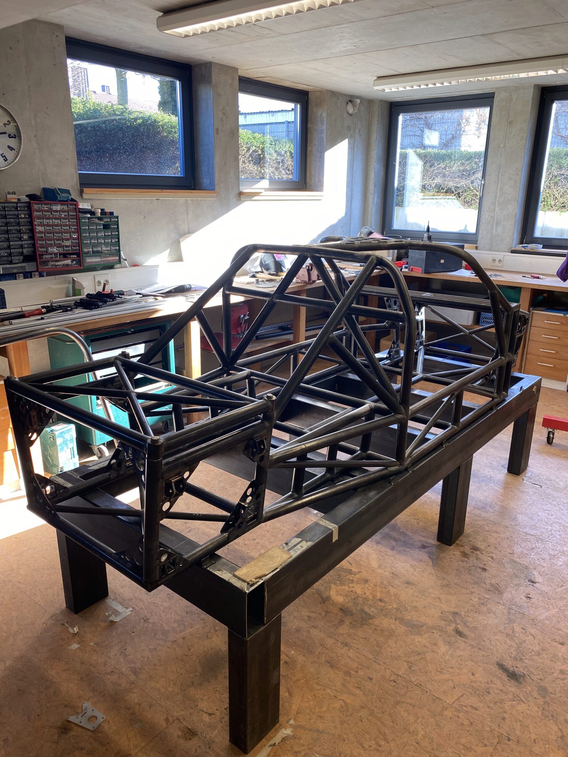
During the development of the frame and the first simulations, I decided to replace the initially planned square tubes in the structurally highly stressed area of the cell with tubes with a round cross-section. There were several reasons for this change: Round tubes are more stable in all directions with the same material thickness and offer significant advantages, particularly in terms of energy absorption in the event of an accident.

But this decision brought with it new challenges:
When I showed the first CAD images of my frame in the GT40s.com forum, an experienced forum user immediately pointed out the significantly higher complexity of building a frame from round tubes. Unlike rectangular or square tubes, which are quite easy to cut and adapt yourself, round tubes run to the center of the other tube at the transitions. This creates complex junctions, especially when several pipes meet. Although these are more stable, they are also more difficult to produce.

At first I dismissed this tip somewhat lightly, as I was planning to have the pipes cut to size using a CNC laser anyway. But as the work progressed, I came across another problem:

Cladding the pipes with aluminum sheet
Attaching the aluminum sheets to round pipes proved to be unexpectedly challenging. For one thing, the bonding surface is smaller on round pipes than on square ones. Secondly, riveting presents additional difficulties:

  • Precision when drilling: The drill bit must hit the highest point of the pipe exactly to prevent it from slipping. This was often a real test of patience, especially in hard-to-reach places, and the drill bit breaks quickly – not fun when the tip is deep in the pipe.
  • Problems with slipping: The 25CrMo4 tube used is much harder than the aluminum sheet, which meant that a slipping drill quickly left an oval and therefore unusable hole in the aluminum sheet.

During the design phase, I decided to use rectangular tubes for the side boxes in which the tanks are housed. From a static point of view, these areas are only attached to the outside of the frame and are hardly stressed during normal driving. Right from the start, the focus here was on passive safety in the event of an accident – a topic that I will cover in more detail elsewhere.

Would I build my frame like this again?
Definitely. Despite the difficulties in production, the switch to round tubes in the central area of the cell was the right decision. Today, however, I would assess the challenges more realistically from the outset and plan more specifically. The gain in stability and safety is definitely worth the extra effort

The basis: from the idea to the digital model

It was clear to me from the outset that I could only really bring the project to life if I first built as complete a CAD model as possible – before I even set a single spot weld. That was crucial for me for two very clear reasons:

  1. Understanding the complexity and finding solutions
    A project like this is incredibly complex, and it was only through a digital model that I could really understand how everything fits together. This was the only way I could develop solutions for all the problems that inevitably arise – without realizing later on that something doesn’t fit. Of course, there were still mistakes, and quite a few – often due to carelessness, a lack of knowledge or simply my impatience, which sometimes made me rush ahead too quickly. But that’s part of it for me. After 4 years of building so far, I’ve become a little more humble.
  2. The need for efficient production
    Most parts of the chassis cannot be produced efficiently without a CAD model. Whether it’s CNC-milled parts, turned parts or laser-cut components – without the digital model, production would take much longer and be much more error-prone.

In the end, only with a CAD model is it possible for me to have an overview of the vehicle in its entirety and ensure that everything fits together seamlessly. This allows me to see all the details of the car before I start building it and to take measurements during construction, etc.

1. digitization of dimensions and data (plans, sketches).

The start of my CAD work was very simple: I began with a 2D plan view and side view to determine the basic dimensions of the vehicle. I used old documents that Ford had submitted when I registered for the Le Mans race. These included basic dimensions such as wheelbase, track width and the overall vehicle dimensions – in other words, everything you need for the initial rough dimensioning.

Using these values, I sketched the vehicle in a simple 2D representation in order to have the most important dimensions clearly laid out on a single document. The advantage of this approach was that I immediately got a clear overview without having to dive straight into the complexity of 3D modeling.

I used TurboCAD for these first steps, as the program offers particularly strong 2D functionality. It allowed me to draw the dimensions precisely and quickly, which was essential for this basic phase. I was able to use this simple template to build everything else later and develop the details step by step.

(You can find an overview of the software I used and still use for the construction here in this article)

2. sources of errorand initial stumbling blocks

My problem was a fundamental one that only really caught up with me when I was building. At the beginning there was a crucial question: Do I design the car from the outside in or vice versa?

For me, this was not really a question at first, because it seemed logical to construct from the outside in. Why? Quite simply – I already had all the necessary GRP body parts, and it was the first step for me to digitize these parts. My friend, who is a scaffolder, had kindly provided me with some scaffolding parts from the house construction, which I used to build a frame – thanks Lars!
I then attached the body parts to this frame and inserted the windshield to align the parts as well as possible.

I discovered that the components could be aligned with each other, but it was unclear whether this alignment was actually correct in relation to the chassis.

To solve this problem, I rebuilt the original aluminum honeycomb sandwich chassis from 19 mm chipboard. Although this involved considerable extra work and additional costs, the effort was more than worth it for me. I mounted the wooden chassis on a sturdy frame made of wooden beams and fitted it with wheels, which made it mobile. After dismantling the wooden chassis, I was also able to use the remaining frame as a practical platform for further assembly.

With this construction I was able to scan the body and thus had a solid basis. Once I had roughly processed the scan, I was able to integrate the body into my CAD model as a reference. I was always guided by the fact that everything I designed on the frame actually had to fit into the body.

So far, so good – but it later turned out that this approach was not the best decision. It wasn’t until last year, when I was working on the steering and the seating position, that I realized that some tubes were in the way, as I had already finished the tubular frame. That’s why I had to retrofit a cut-out in the frame for the steering gear. However, finding suitable positions and mounting points was a particular challenge when designing the seats, as the space was severely restricted by the previously defined body layout. These problems cost me a lot of time, which I could have invested better in retrospect – but more on that later in the relevant chapter.

3.conclusion

Today, I would proceed the other way round: First determine the basic dimensions, then place the body in CAD and then determine the seat and steering wheel positions. I would only start constructing the frame once these parameters have been defined.

My friends in racing still laugh at me, because for them it would have been a matter of course to proceed in this way from the very beginning. Well, you’re always smarter afterwards – but considering that this was my only major mistake in the first three years, it somehow gives me hope