Author: admin

An extraordinary continuation of a motorsport legend

The seven authorized replicas of the GT40 MKIV

Le Mans 1967: Ford celebrated what is arguably its most symbolic victory in the world’s most famous endurance race with the MKIV. A prototype developed entirely in the USA with an aluminum honeycomb monocoque, big-block V8, and aerodynamic body design dominated the race—and finished it with a historic victory. But no sooner had the trophy been won than the MKIV was forced out of the race by rule changes.

The few originals that were built disappeared into collections, museums, and behind locked garage doors. For decades, the MKIV remained an untouchable icon. But two passionate enthusiasts were about to change that: Mike Teske and Ken Thompson


The origin: Teske, Thompson, and a plan that had matured over decades

Mike Teske had been fascinated by the GT40 since the 1960s – a formative experience on a highway south of Pittsburgh, when a GT40 MKI shot past him, left a lasting impression. Over decades, he collected parts, documentation, and contacts. In the 1980s and 90s, he supplied original and reproduced components for restorations – including for Peter Thorp, Bryan Wingfield, and Safir Engineering.

He shared not only a passion but also a craftsmanship with Ken Thompson, a legendary NASCAR fabricator. Both had built a GT40 MKII – now they wanted more.


The initial spark: a discovery in the archives and a crazy idea

The decisive turning point came when Mike was asked to secure old racing documents during an archive relocation at Ford Motor Company. Among them: original drawings of the MKIV and J-Car!

A treasure that almost ended up in the trash – and the beginning of a new chapter.

The plan was quickly decided: not just any replica, but an authentic reproduction—using the same processes, materials, and care as in 1967. The goal: the vehicles should be so convincing that even former Kar-Kraft engineers would have a déjà vu experience.


Mike Teske, Kenn Thompson and the first seven vehicles

Mike Teske took the initiative, together with Ken Thompson and other colleagues, to produce seven authorized replicas of the GT40 MKIV.

Together, they secured original plans, materials, and suppliers—including Ron Fournier (Kar Kraft fabricator from the very beginning) and other veterans of the GT40 era. The seven vehicles were painstakingly built over several years—with faithful-to-the-original bodywork, aluminum honeycomb structure, customized chassis, contemporary parts, and a finish with great attention to detail


2015: Handover to Bob Riley and continuation by Bill Riley

After completing the seven vehicles, Mike Teske handed over the rights to continue the project in 2015 to Bob Riley, one of the most renowned chassis developers in the USA – and himself part of the original Kar Kraft team

Bob commissioned his son Bill Riley to continue the MKIV project. The company Riley Technologies has acquired the Kar-Kraft assets, including tools, jigs, molds, and technical drawings, and plans to produce up to 10 more continuation cars of the MkIV.

Bill Riley runs the website www.karkraftmkiv.com and is deeply committed to building cars, preserving historical vehicles, and passing on this technical cultural heritage.


Exclusive insights – straight from the source

The images shown in this article come directly from Mike Teske collection. They not only show details of the seven vehicles, but also rare shots from the manufacturing process: from the first chassis buck to the painting of the last finished MKIV.


A personal thank you

This post would not have been possible without the help of Petr, a reader of this blog. Petr put me in touch with Mike Teske and organized all the images—for me and for you.

Thank you very much, Petr!

The rims

Rims – buy or make them yourself?

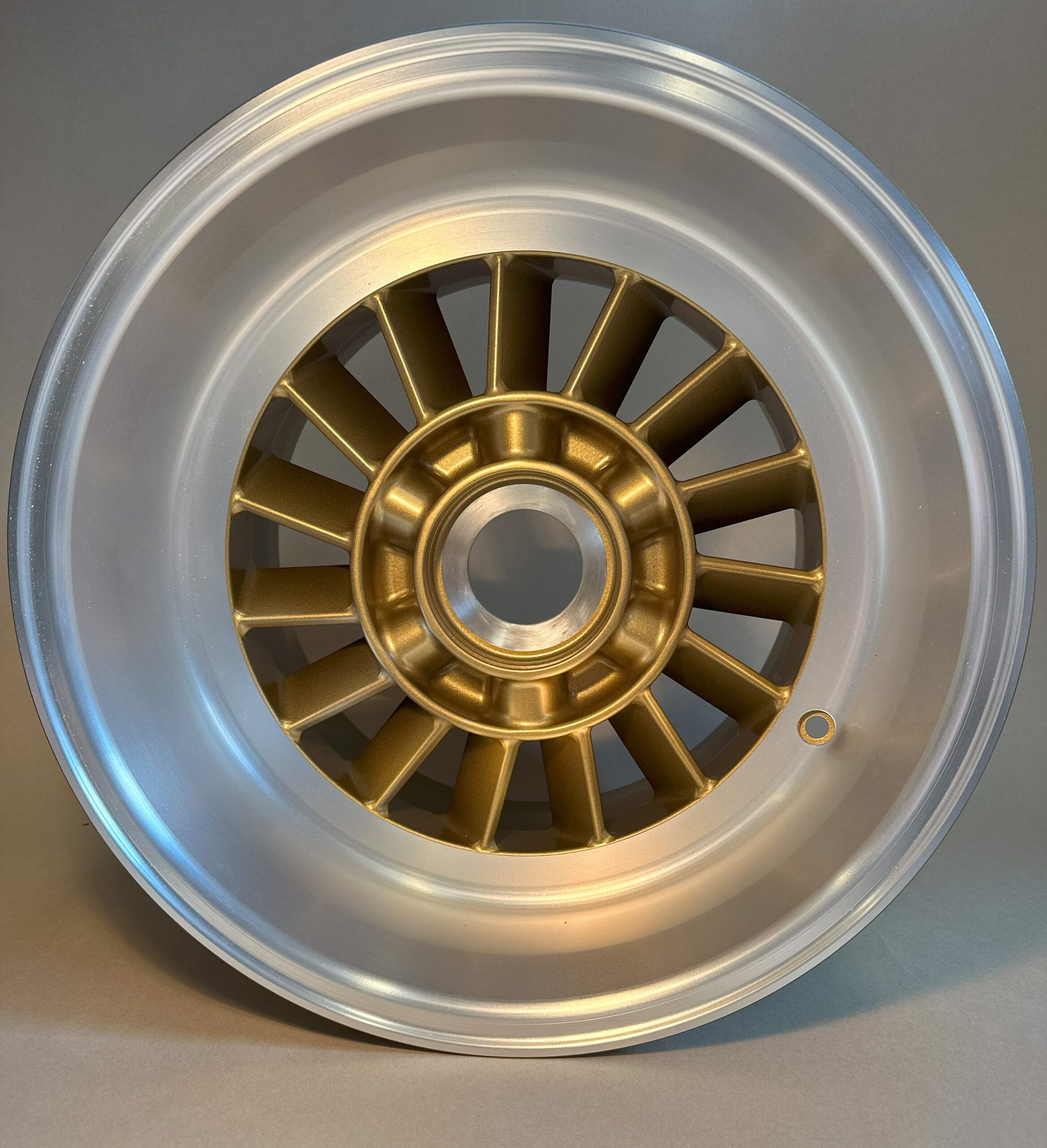
Rims are one of the most striking features of the GT40 MIKV. During the construction of the chassis, I also experimented with more modern 17” rims. These would have provided more space for the suspension and brakes. But in the end it just didn’t look good, as it made the proportions of the whole car look inharmonious and the classic look of the GT40 was lost. That’s why I stuck with the original dimensions – 8.5×15“ at the front and 12×15” at the rear. Even though this presented some additional challenges, it was only a small step to the decision to adopt the original design as far as possible.

1. Buy or make yourself?

Currently, I only know of one manufacturer from which you could possibly buy such rims: RaceCar Replica (RCR) from the USA. My acquaintance Morton Larsen from England owns a set and was kind enough to send me numerous pictures of it. Unfortunately, I was not convinced by the quality. The milling marks are clearly visible, which would require extensive reworking such as grinding, polishing and coating to achieve an appealing appearance and the desired surface quality. In addition, these rims are tied to the RCR mounting system – not an option for me. The price including import to Germany is also not insignificant, and my previous experiences with RCR were not particularly good.

However, Morton not only sent me pictures, but also detailed measurements. That was the deciding factor: a new design was needed.

2. rim design

Designing wheel rims is a complex task. It’s not just about the design, but also about numerous technical details: What should the wheel mounting look like? What strength is needed? A wheel offset to match the kinematics of the chassis. How should the tire contact surface (hump) be designed? And much more.

At first, I wanted to make it easy for myself and build a three-part rim. The distinctive center with the fan blades was to be CNC-milled, while the front and rear rim halves would be bolted together. But after I had designed it that way, I realized that the visible screws didn’t look good. So I decided on a two-part construction with the screws hidden on the inside. However, this increased the milling effort considerably, especially for the deep wheel arches on the rear axle.

I was able to obtain the required multi-part wheel rims from a supplier of BBS wheel rims. But on closer inspection, the quality was disappointing – in particular, the contour of the tire contact surface with the hump did not meet DIN standards or my expectations. So I finally decided on a monoblock rim that was milled out of a single piece of metal.

In doing so, I also had to deal intensively with the central locking system. At first, I thought of the usual adapter plate solutions until I came across the manufacturer “ZETA” from Swabia. This company offers ready-made central locking hubs that are also used in GT3 racing by Porsche and other manufacturers. I will write a separate post about this.

Ultimately, I revised the rim again – for the umpteenth time. The result may not be the lightest, but in terms of quality and durability, it absolutely meets today’s racing standards.

3. contract manufacturing

Once the design was finalized, I had to find a suitable manufacturer – a company that could take over the entire process from quality assurance and strength calculations to production and coating. And all this had to be as affordable as possible and for just a single set!

From my network, I kept hearing about the high costs of design studies in this area – even for rims that are supposed to be visually convincing but don’t have to meet any technical requirements. But through my contacts in racing, a small company in Spain that manufactures small series for Formula 1 and numerous motorsport teams was recommended to me: Goyarfw.

This high-tech company near Valencia impressed me from the outset with its expertise and helpfulness. After analyzing my CAD data, they found a few modifications I needed to make. For example, the turbine blades in the wheel center had to be opened about 15° further to ensure that there was still enough space for the milling head on the deep rear wheel rims. The revised design was then subjected to an extensive strength analysis to ensure the required safety.

In addition to the pure quality, the manufacturing accuracy also gave me a headache. My bobbins – the five cams of the rim on the inside – should be manufactured with a tolerance of only 3/100 mm. Both the hub manufacturer and the rim manufacturer had to guarantee this, otherwise the five round cams would not fit exactly into the intended holes. It was not just about the diameter, but also about the bolt circle and the exact distribution.

Why such a narrow tolerance? In racing, 1–2/10 mm is usually the norm here to enable a quick wheel change. However, this larger tolerance quickly leads to so-called “micromovement”: when accelerating – especially with an engine with over 730 Nm of torque – the round hole gradually becomes oval due to the constant loads. In racing, these rims are replaced after a season, but for me that was out of the question. Since I don’t have to perform quick pit stops, precision was more important to me than quick assembly.

In the end, my concerns proved to be unfounded. The rims and hubs were manufactured with such high precision that everything fit perfectly. As additional proof of quality, I received a comprehensive measurement protocol with the delivery, which showed compliance with all specifications.

Conclusion

I could go on writing many more details about the challenges of designing and manufacturing wheels. But it should be clear even so that it is no easy undertaking. You need a lot of knowledge – or you know the right people to ask.

If any of you are also thinking about making your own rims, feel free to contact me. Goyarfw and I have now entered into a small partnership. This means that I can not only facilitate the construction, but also the production.
Suspension: hub carrier and wishbone

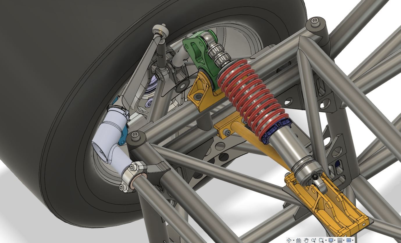
The wheel suspension of the GT40 MKIV was one of the biggest challenges in the design of my vehicle. The extremely tight space conditions, caused by the small but wide 15-inch rims, made particularly clever and precise planning necessary. Numerous design approaches were tested, rejected and revised until I finally found a solution that I was really happy with. The result is a technically mature, weight-optimized and extremely resilient wheel suspension that meets the requirements of a high-performance vehicle.

Design of the hub carrier and wishbone

Clearance and kinematics

The basis of the car’s suspension is the chassis kinematics, which defines the six pivot points of the wishbones – four on the chassis and two on the hub carrier. These fixed points are essential for driving behavior and are defined in the kinematics. So I had to build my entire design around these points, taking many factors into account:

  • The limited inner space of the rim
  • The position of the mounting points for the steering lever and brake caliper
  • The wheel bearing used is from the Audi R8.
  • The position of the frame tubes
  • The maximum steering angle required
  • The necessary freedom of movement for all components under load

I ran through many designs in CAD, but it was only with extensive FEM simulations that I was able to develop a structure that works both mechanically and geometrically.

hub carrier: high-strength aluminum construction

The Hub’s are among the most complex components of the car’s suspension. I decided to use high-strength 7075 aluminum, which is CNC-milled. The shape was a constant balancing act: on the one hand, it should be as light as possible, but on the other hand, it should not lose stability. A design that was too delicate would have increased the risk of breakage, while an oversized construction would have added unnecessary weight. In the end, I found a geometry that was optimized by FEM calculations and offered an ideal balance between stability and strength.

In addition, numerous connections such as the mounts for the university ball joints, the connection of the steering lever and the brake caliper mount had to be precisely integrated. In this case, coordination with the wishbone design was particularly crucial to ensure that everything would fit together perfectly later on.

Wishbone: welded lightweight construction

I made the suspension arms out of high-strength 25CrMo4 steel tubing with a diameter of 35 mm and a wall thickness of 2 mm. I thought long and hard about whether aluminum or titanium would be a better alternative, but steel simply offers the best combination of strength, weldability, and ductility – exactly what I need for racing. And it’s affordable… 🙂

The challenge in building the wishbones was mainly in the welding. To precisely maintain the geometry and avoid warping, I made CNC-milled wooden templates. I was able to insert the individual tubes and weld-in sleeves exactly into these and tack them before everything was finally welded. This method proved successful and ensured that the control arms had exactly the dimensions they should have in the end.

Additionally, I integrated some details to save weight and increase stability at the same time:

  • 1.5 mm thick gusset plates made of 25CrMo4 to reinforce the highly stressed areas
  • Precision welding sleeves made of the same material, with an internal weight-optimized dumbbell shape
  • High-quality motor sports uniball joints with play-free pretension, available almost everywhere from the company ASKUBAL.
  • High-strength dowel screws that have been additionally machined for the clearance-free assembly of the transverse control arm bearings

The entire process was extremely laborious and took countless hours of planning, testing and optimization. But in the end, I have a chassis design that not only works, but also meets my quality and performance standards.


Chassis: From the idea to the design

Development and design of the chassis geometry

The suspension design was one of the crucial points of my project. As I deliberately decided against a pure reproduction of the original Ford GT40 MKIV chassis, I had to find a solution that harmonized safety, performance and historical appearance. This meant modern kinematics in a classic body.

The basic decision was made quickly – the suspension was to be based on current GT3 standards. The challenge was to design a geometry that would not only bring the enormous performance values of my vehicle safely onto the road, but also offer a manageable balance between agility and stability. At the same time, it had to fit into the given installation space of the body.

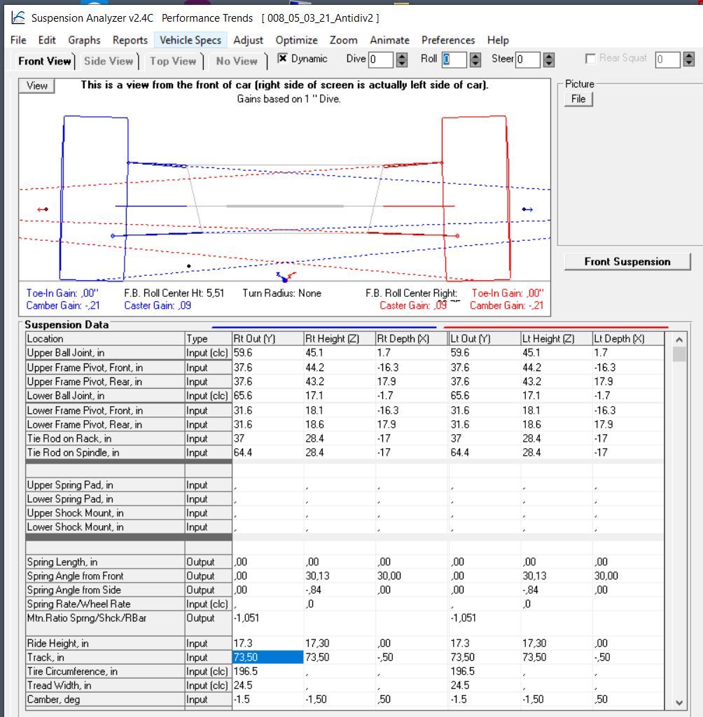
The first step was to work out the basic parameters: Track width, wheelbase, caster, camber, roll center and anti-dive/anti-squat parameters. It was important to me that the vehicle had direct yet controllable handling – especially at high speeds. The absence of electronic driving aids made a clean mechanical balance all the more important.

The anti-roll bars are an often underestimated but essential part of the suspension setup. At the front, I use a 7-way adjustable anti-roll bar from the Porsche 992 GT3 RS factory racing car. It fitted so well, it was as if it had been specially developed for my vehicle. At the rear, I use the stabilizer bar from the Porsche Cayman GT4 racing car, also 7-way adjustable, but we had to adjust the width. Originally, I didn’t want to plan with these high-quality components, as they are quite expensive, but my friend Uwe Bleck convinced me with the words: “This will take your suspension from the 20th to the 21st century.” Only the road and the race track will show whether this decision proves successful.

Optimizing the kinematics through simulation

Once the basic chassis design had been defined, the next step was fine-tuning. With the help of simulation software, various setups were tested in order to further optimize the handling. The simulations helped to analyze critical parameters such as the deflection curve, steering geometry and dynamic wheel load distribution.

The evaluation of the roll center in different driving situations was particularly important to me. By making specific adjustments to the wishbone lengths and angles, I was able to further refine the suspension so that it offers stable yet agile handling. In addition, the simulations allowed for more precise tuning of the damper and spring characteristics, which means that the car will feel optimal both on the road and on the racetrack.

This iterative optimization has proven to be a crucial step in unlocking the full potential of my suspension.

Development and design of the suspension including dampers

With the geometry as a basis, the detailed work on the suspension began. As the original suspension of the GT40 MKIV had some weak points in terms of safety and driving stability, I opted for a double wishbone design to ensure the most precise wheel guidance possible. A normal damper arrangement at the front and a pushrod system at the rear.

The wishbones were dimensioned in such a way that they offer maximum rigidity with the lowest possible weight. I used original Audi R8 wheel bearings as the basis for the design – this had the great advantage that I could also use the joints from the original drive shafts to match my R8 gearbox.

Another critical point was the choice of dampers and springs. The combination had to perfectly match my vehicle weight, the axle geometry and the intended use. Here I opted for an adjustable damper system, which allows me to try out different setups. The positioning of the spring/damper units required special care – both in terms of the lever arm and accessibility for later adjustments.

My friend Toni Pfeifer from Pfeifer Fahrwerkstechnik helped me a lot here. He is a gifted damper developer and also produces them.

After numerous calculations and simulations, I hope to have found the optimum combination. I believe that my suspension will not only be safe on the road, but will also offer a driving experience that strikes the perfect balance between old-school racing car and modern performance vehicle.


This part of the project was a real challenge and took a lot of time. But that’s what makes it so appealing to me – finding the right mix of technology, history and modern engineering.


First CNC milled parts

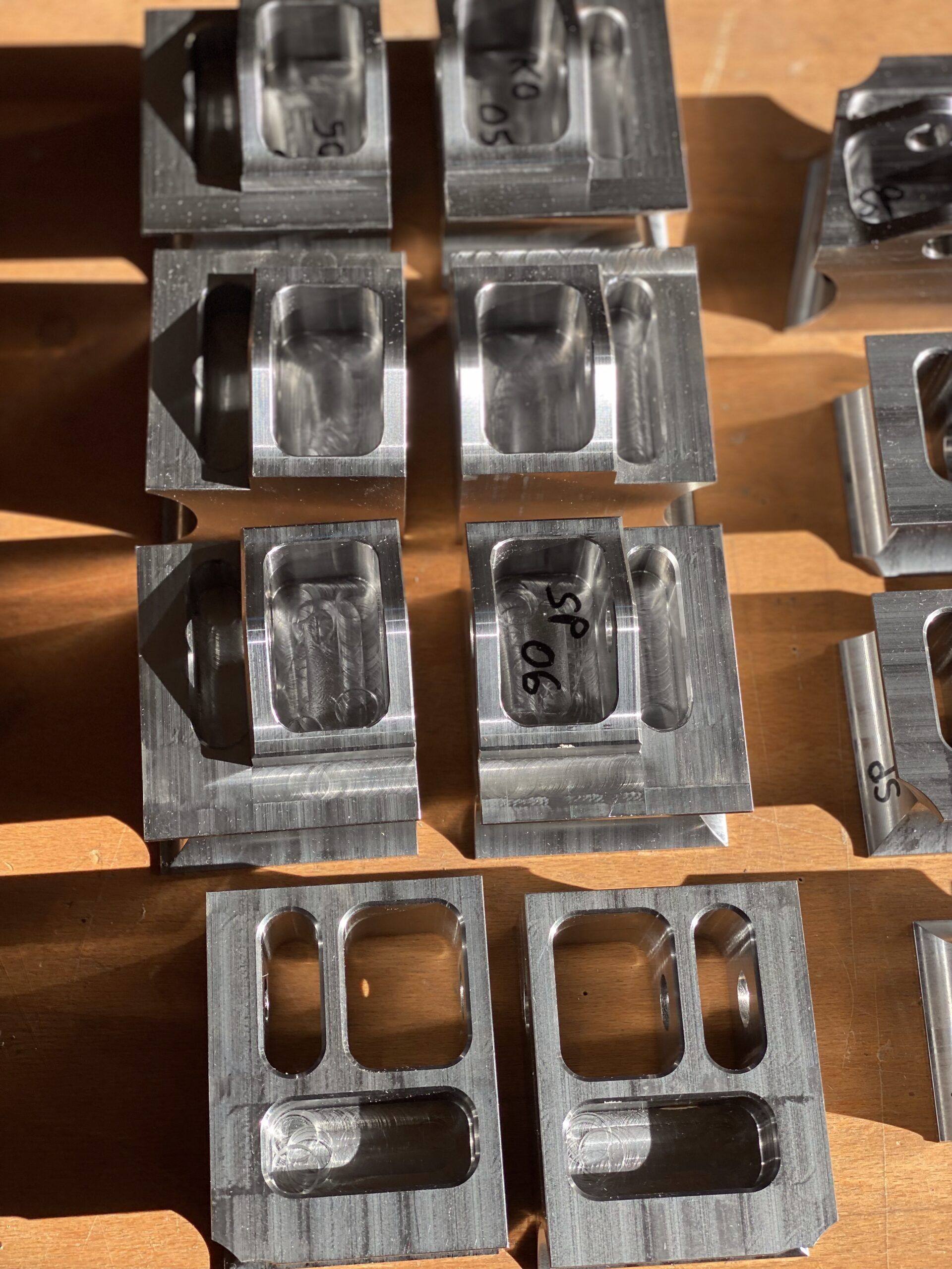
Load-compatible brackets for the wishbone mount

Why I am not compromising here

I said to myself right from the start of this project: if I’m going to build something, I’m going to build it properly. In my opinion, many replicas are particularly sloppy when it comes to the wishbone mount. There are often simple designs that are neither load-bearing nor durable in the long term. I wanted to make it better – safer, more sophisticated and simply so that I can sleep peacefully at night when the car is on the road or track later on.

The CNC-milled parts and their contribution to stability

For the wishbone mounts, I designed brackets made of 25CrMo4 (chrome-molybdenum steel, like the frame) and had them CNC-milled. I also used special weld-in sleeves, also made of 25CrMo4, which harmonize perfectly with the brackets and can be seamlessly integrated into the frame structure.

That may sound like a lot of effort – and it was – but it was important to me that the forces acting here were introduced cleanly into the overall structure. The loads at this point are enormous, and a poor design is not only a weak point, but potentially life-threatening.

Integration into the framework

For me, the integration was not just about stability, but also about the entire frame geometry being adapted to it. You don’t just do a detail like that “on the side”. It was important to me that the brackets were not only stably attached, but that the loads were distributed and that the entire frame absorbed these forces properly.

Why I am making this effort

Sure, these parts are expensive to make, but at the end of the day they are life insurance. I’m building this car because I enjoy it and I have certain expectations of myself. It’s not enough for me if something is just “adequate” – I want it to be really good.

A comparison with the big players

To show what is possible: I have included a picture of an LMP1 racing car from 2019 at the bottom of the picture gallery. Here you can see how modern 24-hour racers design this area. The brackets of these vehicles are designed for loads of ±35 G – that’s obviously a different league, but it shows what’s important: load-appropriate designs are the key to safety and performance.

Conclusion: No compromises on safety and stability

I know it was all a lot of work, but in the end I’m happy every time I look at these parts and know that they work – and that they work as they should.
Only Erwin always cursed because of all the gussets 🙂

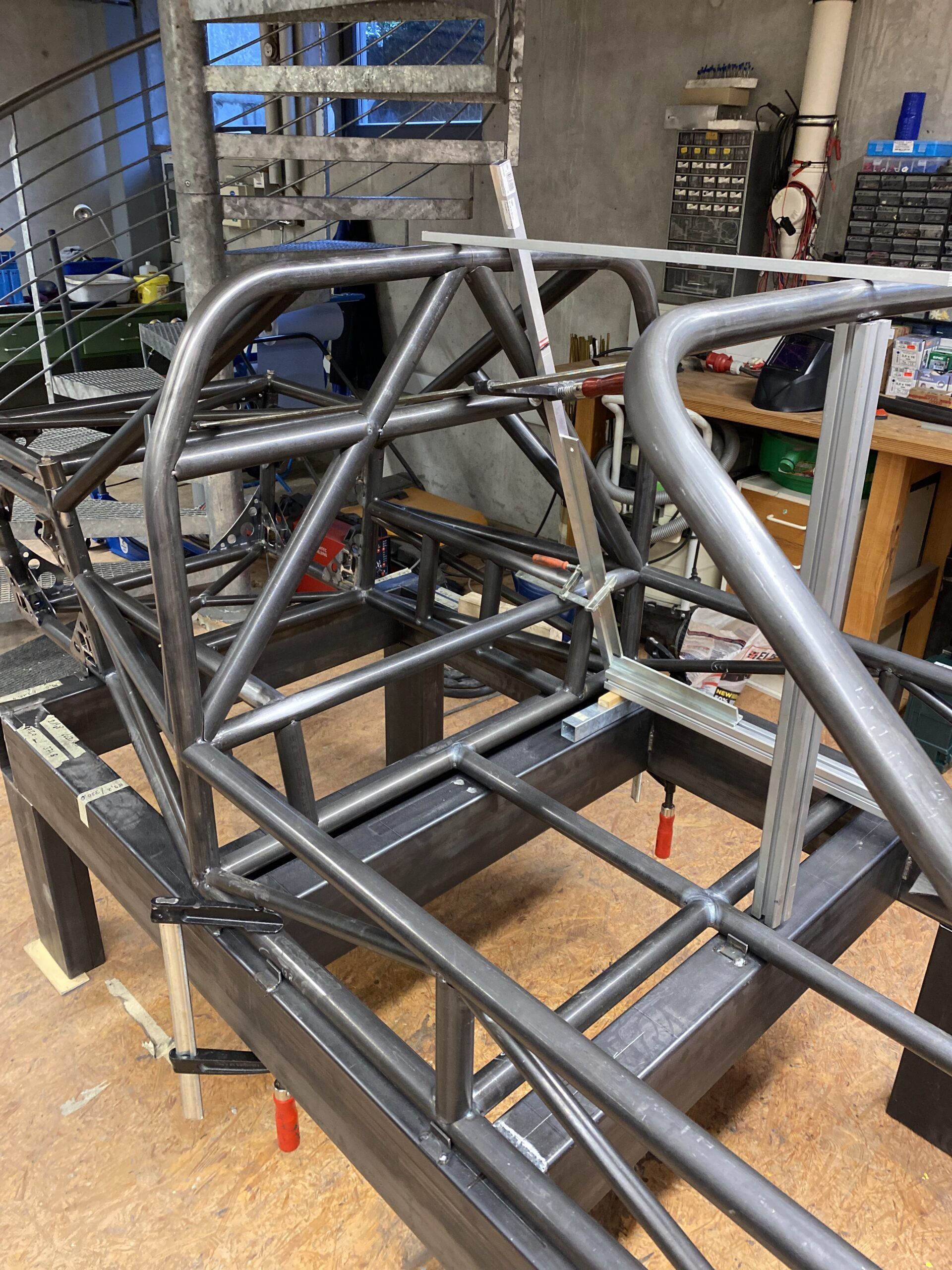
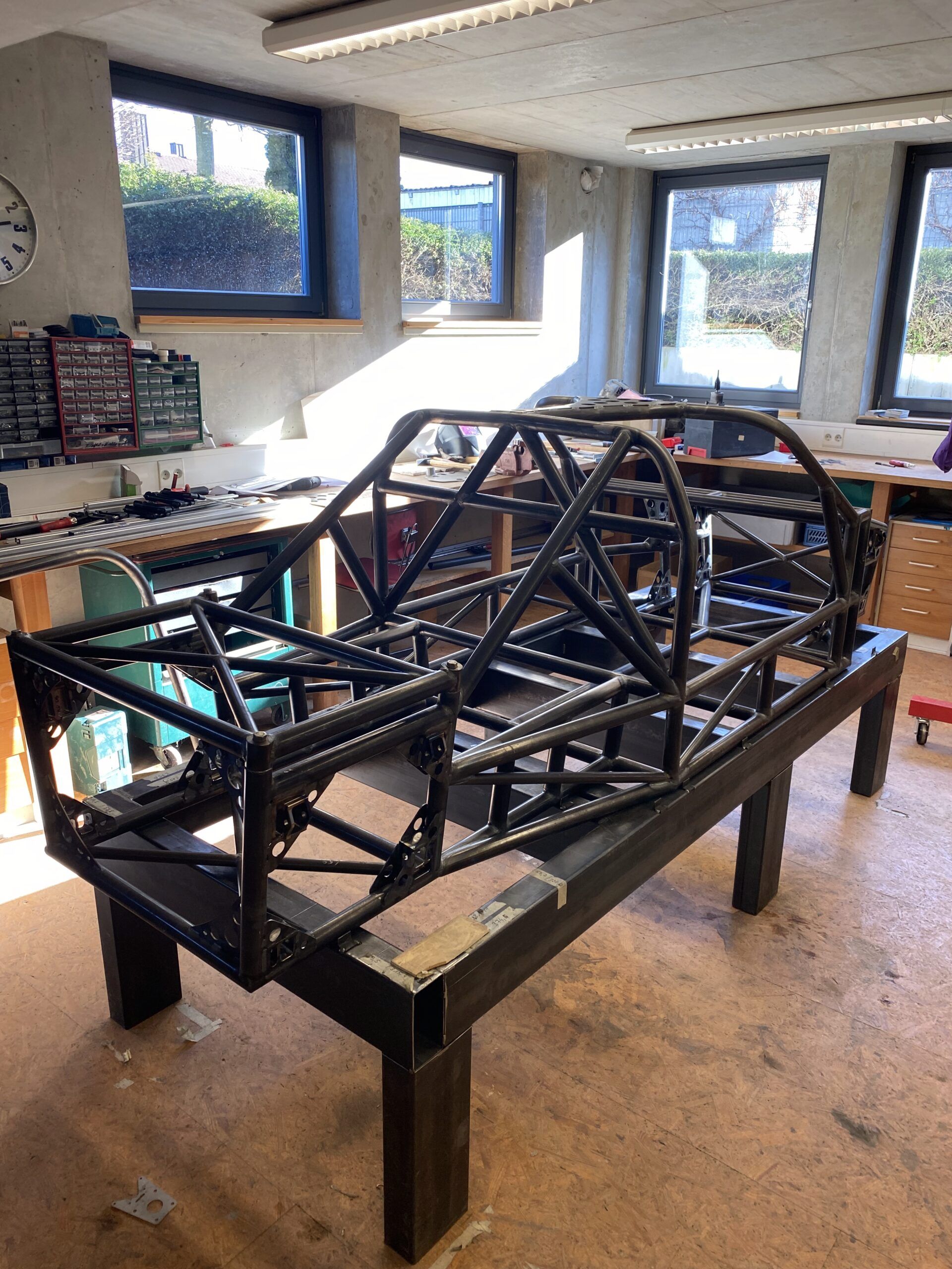
The frame construction

Tubes

First of all, I would like to briefly explain the different tubes that make up my tubular lattice frame.
For my frame I used 25CrMo4 tubes, which are widely used in racing. These tubes are readily available from specialized dealers for the motorsport sector. I bought mine from motorsport-metall.de, the web store belongs to the company TENNANT GmbH. The tubes are available in lengths of 4 – 6m.
The structural steel often used by replica builders has a tensile strength of 300-400 N/mm², whereas the tensile strength of 25CrMo4 is between 800-1000N/mm², i.e. more than twice as much!
This higher strength makes 25CrMo4 ideal for applications that require high load-bearing capacity, such as in motorsport.

Pipe dimensions used

I mainly used 40×2 mm and 25×2 mm tubes, which are a common size in frame construction. In retrospect, 35×2 mm tubes might also have been sufficient. However, I would then have had to design and, above all, simulate a completely new version of the frame, which would have been too much work for me.
At the beginning, my frame weighed about 160 kg in the first designs in the CAD program. After more than 100 new designs with optimizations and simulations, I was able to reduce the weight to about 98 kg with the 40 mm tubes. The 35 mm tubes are around 14% lighter, which would have brought me down to around 85 kg. But I didn’t want to go to all the trouble of redoing everything.

The 25×2 mm tubes were used for the tension struts for bracing. I built the two side boxes at the top from 30x30x2 mm square tubes, while the bent ribs are made from 30x15x2 mm tubes. These side boxes do not contribute to the rigidity of the actual frame and are therefore kept as simple as possible.

Precise cutting of the tubes

As already described in the corresponding article in the “Construction” section, I had all the tubes cut using a laser CNC machine. A big thank you goes to Alex, who even added small rectangular lugs to my CAD data that fit into corresponding cut-outs in the counterpart. This made alignment even easier – a great idea!
I also had to make an exploded view of the frame and assign a number to each tube. Alex then engraved these numbers into the individual tubes with a laser during the cutting process. However, the engraving was difficult to read on some of the tubes, which resulted in a lengthy search to find out where they belonged. The frame consists of almost 100 tubes, so it’s easy to lose track.

Welding the frame

Perhaps a few words about welding.
I can only do gas-shielded arc welding (MAG) myself, and not particularly well. However, the TIG process is usually used on frames like this. This is where I enlisted the help of my friend Erwin, a pensioner with a lot of time on his hands and plenty of experience. Watching him weld was a real pleasure. Not only that the weld seams look like each other, but especially the way he welds.
First weld on one half of a pipe, bending it in the direction of the weld seam, then let it cool down and weld the second half. And as if by magic, the pipe bends back into its original position – amazing! That takes decades of experience.

Stress-free annealing of the frame

I actually wanted to let the frame anneal stress-free after welding. But firstly, I couldn’t find an oven that would fit my frame, and secondly, this was at a time when energy prices were skyrocketing. The suppliers almost tripled their prices within a few months.

Conclusion

To build such a frame, you need a lot of skills and knowledge, although it remains to be seen whether you really have to do it as elaborately as I did.
I am more than satisfied with the result and would like to thank Erwin and Alex once again!

My welded frame – the basis for the frame

The first step in building my GT40 MKIV was to create a stable base. To do this, I built a welded frame that exactly matched the dimensions of my frame. The construction consists of rectangular tubes (80 x 160 x 3 mm) and had the following dimensions:

  • Length: 2061 mm
  • Width: 1045 mm
  • Height: 600 mm

The dimensions of the welded frame are based on the layout of my tubular lattice frame. They not only provided stability, but also the optimum accessibility I needed for the welding work.

Precise alignment thanks to laser technology

To ensure that the frame was built correctly, I measured the lowest level of the frame tubes very precisely with a laser. This precision was crucial to avoid distortion stresses later on.

Fastening with a simple system

I used small angle irons to fix the frame tubes: 20 x 20 x 2 mm, cut into 20 mm long pieces. I attached these strategically to the welded frame and fixed the tubes to them with a few spot welds. The angle pieces held everything firmly in place while I built the frame step by step.

After completing the frame, I was able to simply bend the angle irons. This approach proved to be absolutely successful and meant that the frame was practically free of distortion and tension.

My conclusion

An accurate, distortion-free and stable welding frame is a crucial aid during preparation. Of course, a proper welding table would have been even better, but unfortunately it is also very expensive in this size. But even so, I was able to work with the necessary stability and precision to assemble the frame cleanly and without compromise.


Fuel supply: Tanks and safety

Safety aspects of fuel supply

In the GT40, the position of the tanks is determined by the original design—they are located in the voluminous side skirts. Since I don’t need this area in my design to stabilize the frame, as is the case with the original, I had a little more creative freedom here.

There are also differences from the original in terms of the amount of fuel required: while the GT40 was equipped with the largest possible fuel tanks for 24-hour races, a capacity sufficient for about an hour of racing is enough for me.

Of course, at the beginning, I thought long and hard about using special safety tanks, known as fuel cells, such as those offered by ATL. However, finding suitable long and flat models proved extremely difficult. Most prefabricated tanks were either too tall or too wide to fit into the sills. Although it is possible to have such tanks custom-made, the price per unit is at least €2,000 – often even higher.

Another aspect that spoke against the immediate use of fuel cells was their limited service life: these tanks are usually only approved for five years, as the inner rubber cell has to be replaced regularly. For me, this meant that the approval might have expired before my car was ready for use.

So I decided on a compromise: I designed tanks made of 1 mm thick stainless steel sheet. These are equipped with baffles to stabilize the fuel when cornering. I also integrated maintenance hatches so that the tanks can be filled with tank foam after welding.

To further increase protection, each tank is attached to a surrounding, welded stainless steel band. This bracket is screwed to the most solid part of the side boxes, the top, with four M8 screws each. I deliberately left as much space as possible between the brackets and the outside of the sills to gain additional space and protection.

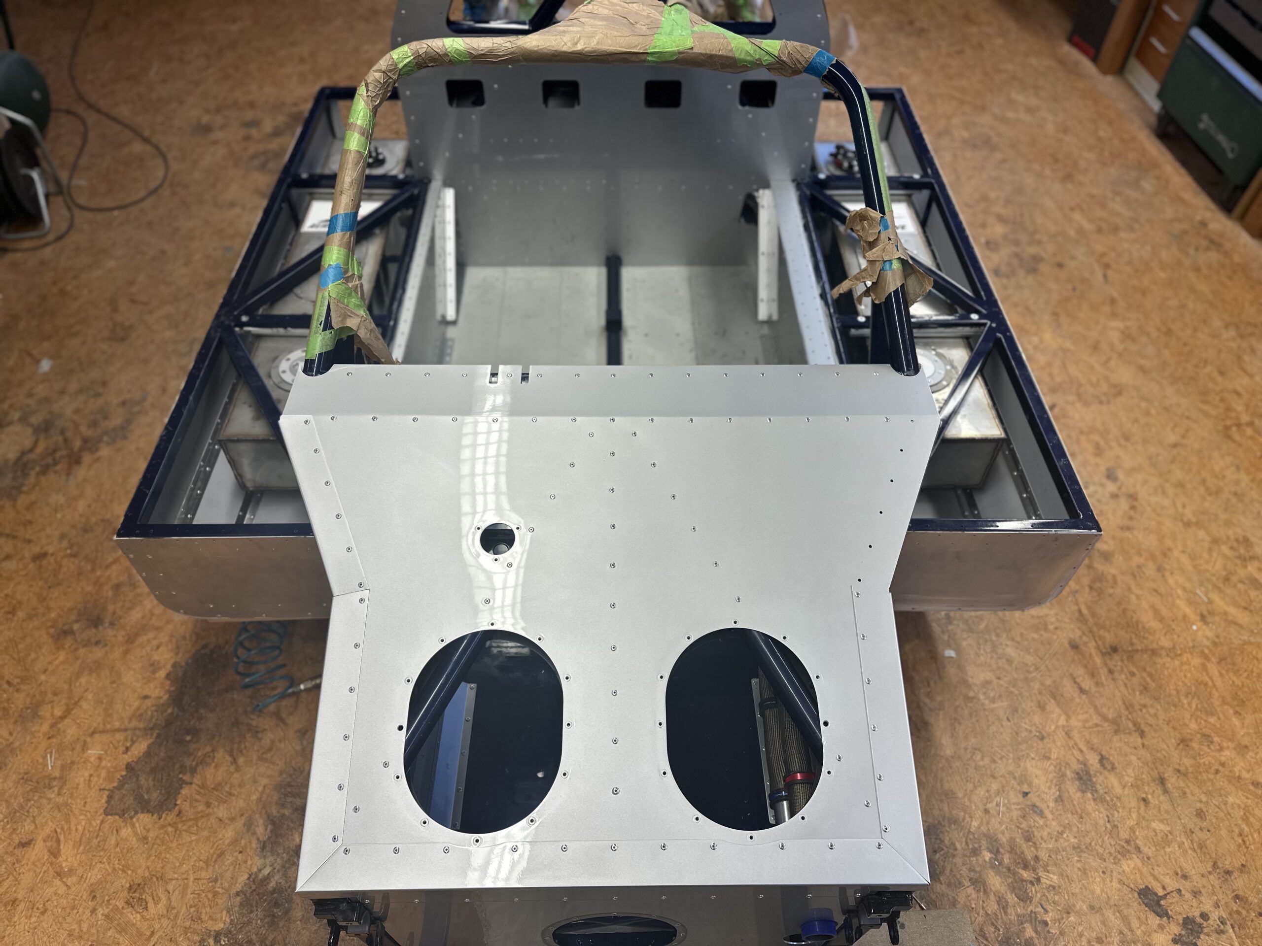
I reinforced the inside of the aluminum cladding on the sills between the solid, curved steel beams with 10 mm thick aluminum honeycomb sandwich panels. These panels are glued flat and supported by a 45° angle piece that reinforces the transition from the floor panel to the side wall. This construction serves purely as a crash structure and is designed to absorb energy in the event of an impact.

Of course, there is still a residual risk—that’s the price you pay when you rebuild a race car from the 1960s. Back then, people were much more willing to accept risks than they are today, and as we all know, enough went wrong.

Construction of fuel tanks

For the fuel tanks, I deliberately chose 1 mm thick stainless steel sheet, as I was advised against using aluminum due to modern types of gasoline. Aluminum tends to corrode when used with today’s fuels, which I wanted to avoid at all costs. The tanks each measure 1155 x 220 mm with a height of 156 mm.

Inside the tanks are three baffles that do not reach the top and have five 30 mm holes each at the bottom of the tank. This design divides the tank into four chambers that stabilize the fuel during rapid changes of direction. To fill the tanks with tank foam, I attached three removable lids to the top. These are large enough that you can easily reach into the chambers with your hand.

The tanks are secured using two welded stainless steel straps per tank, which are additionally stabilized by brackets. Four M8 rivet nuts per tank enable secure yet removable fastening.

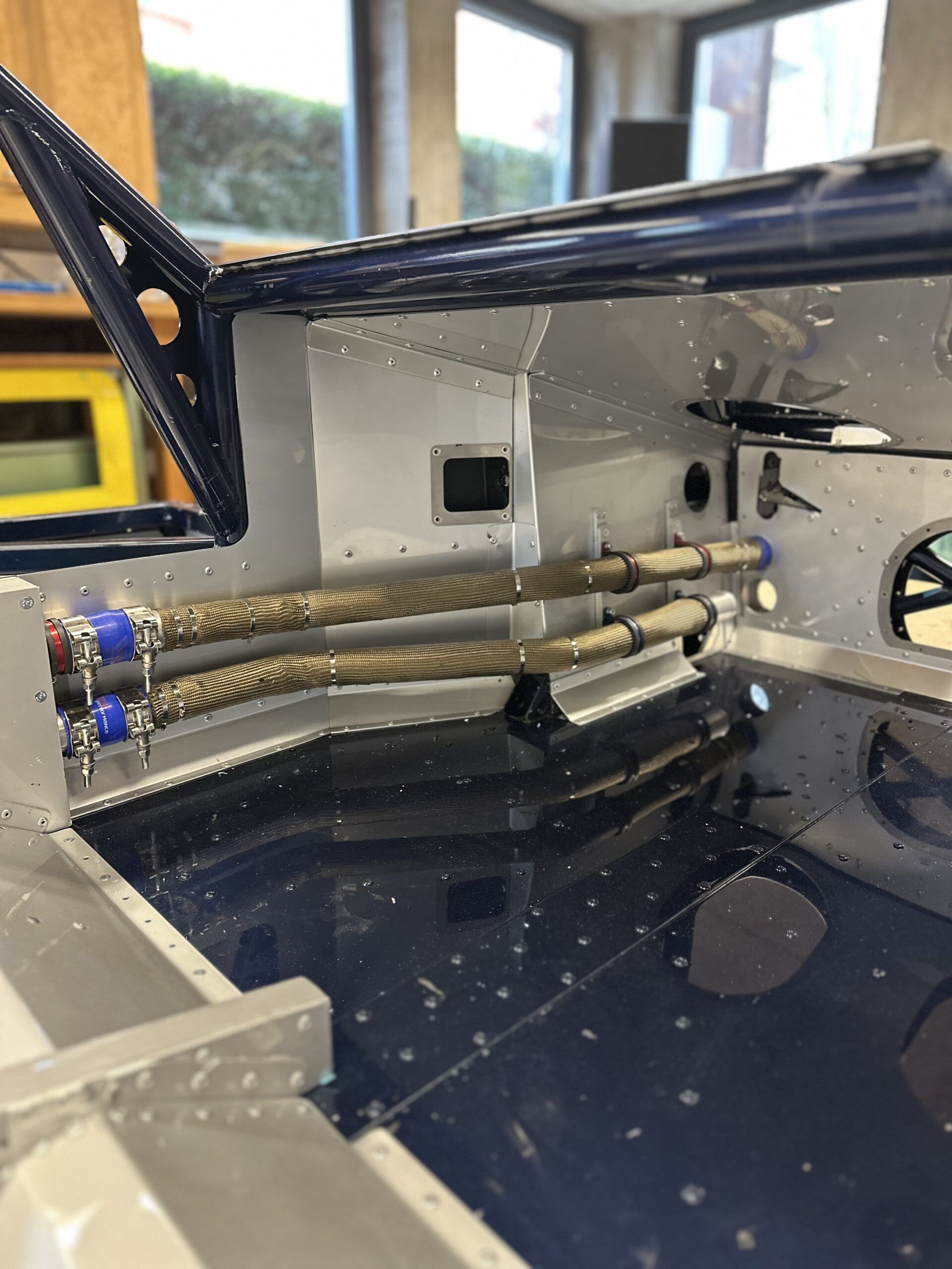
To connect the two tanks, I used two Dash 16 lines that run along the engine compartment side of the fire wall. In the original design, an 80 mm pipe was used for this purpose, which ran under the backrest in the passenger compartment—an unacceptable safety risk in my opinion. Splitting the line into two smaller lines was necessary for space reasons, but it also provides significantly greater safety.

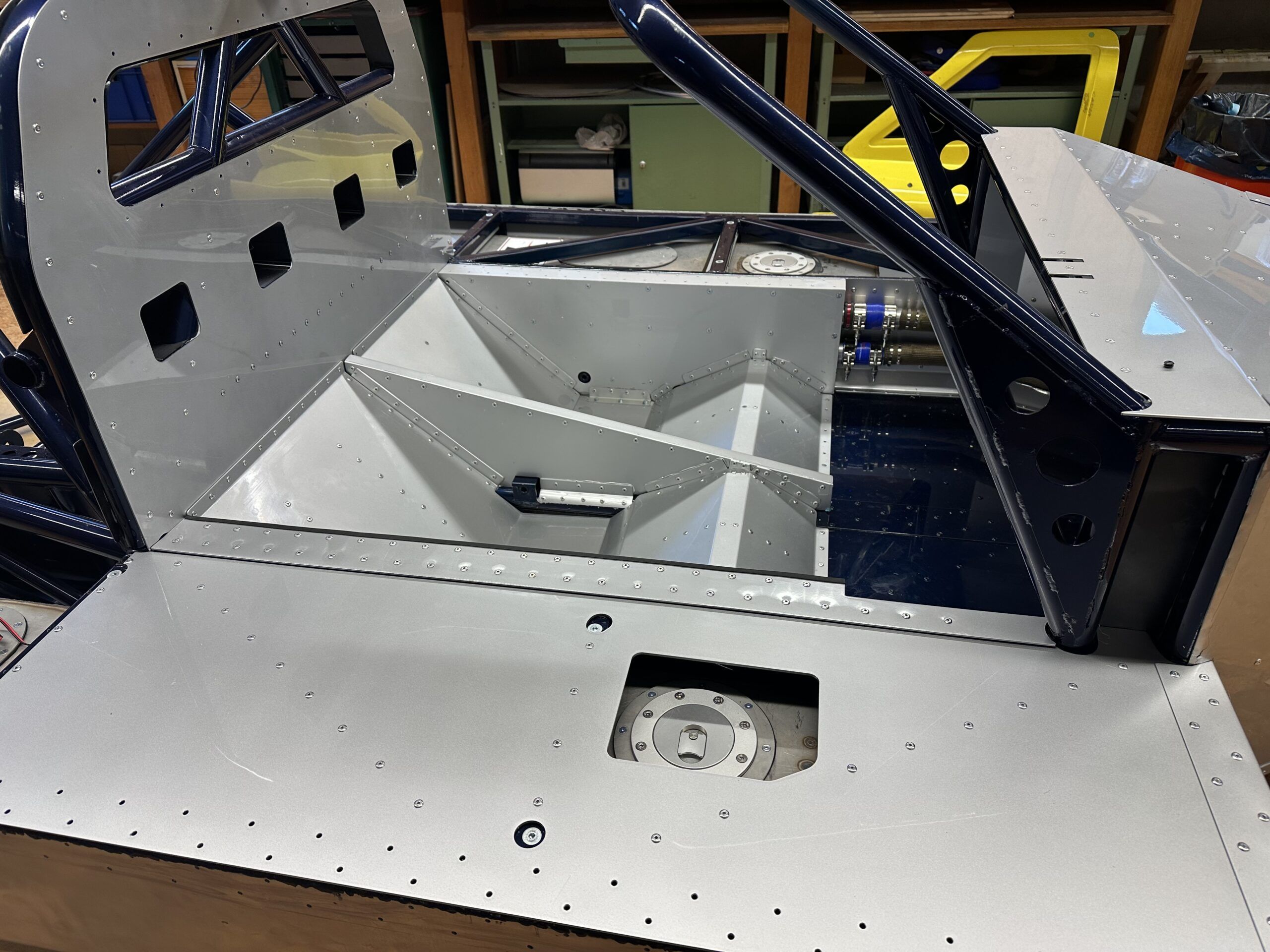
Both tanks have their own fuel caps, which are mounted directly on the tanks. I don’t need a quick-fill device, so refueling is done separately on the left and right. The left tank contains the sensor for the fuel gauge, while the right tank houses the internal fuel pump.

After welding and before filling with safety foam, I filled the tanks with 0.6 bar pressure and carefully checked them for leaks using leak detection spray. Special care must be taken here: 0.6 bar may seem low at first glance, but the pressure acts evenly on the entire inside of the tanks and generates considerable forces. In fact, I noticed a slight “bulge” during this step.

To ensure that the pressure does not rise too high, I have installed a special cover on the access holes with an automatic pressure valve from the heating industry. This valve blows off precisely at 0.6 bar, providing additional safety during testing.

Pump system and pipes

The topic of fuel pump systems alone could fill entire books—or at least extensive discussions such as those on the GT40s.com forum. The relevant posts there examine all conceivable possibilities and aspects in detail. If you would like to take a closer look, you can find the posts here.

In this section, I would like to limit myself to my personal approach. As with the cooling system, I wanted the simplest possible design; I can always change it later if I deem it necessary.
Therefore, I have decided to use a single fuel pump for the time being.

My engine is powered by a classic Holley carburetor—for reasons of originality, appearance, cost, and, last but not least, its characteristic sound. After the break-in period and initial test drives, I could switch to a fuel injection system such as the Holley Sniper System, but programming fuel injection seemed too complicated for me to start with.

When redesigning a race car, you should always make sure to keep the design as simple as possible at the beginning. Even in a simple system, there are still plenty of potential sources of error. Individual areas can be easily optimized later on once the vehicle is running reliably.

The decision to use a carburetor has one key advantage: I can operate the tanks without pressure. This simplifies both ventilation and eliminates the need for a return circuit. I use the Phantom 200 Stealth Fuel System from Aeromotive as the pump, supplemented by the appropriate dash adapters, filters, pressure regulators, and other accessories. You can find the connection diagram I used in the image gallery below.

The lines used consist of high-quality hoses encased in steel braiding. These not only offer high pressure resistance, but are also extremely heat-resistant—a standard that should be a given in racing cars.

With this setup, I will try to get the car up and running reliably. As already mentioned, changes and optimizations remain possible at any time. After all, it is only during operation that it becomes clear where fine-tuning is necessary. We’ll see…


The cooling system of the GT40 MKIV: challenges and solutions

Planning and designing the cooling system for my Ford GT40 MKIV was one of the more complex tasks I faced. The limited space in the engine compartment, the requirements of a powerful V8 mid-engine and the desire to preserve the original appearance of the vehicle posed particular challenges.

Positioning the coolers and pipes

A major problem in the design of the cooling system was the extremely small engine compartment. A conventional mechanical water pump simply wouldn’t fit. After intensive research, I decided to switch to an electric water pump. The forum recommended two manufacturers who offer pumps for high-displacement engines: Pierburg (Germany) and Davies Craig (Australia).

Both manufacturers kindly provided me with CAD data, which helped me with the planning. I would have liked to use the Pierburg pump, but it could not be integrated into the overall system in a flow-optimized way. In the end, my choice fell on the Davies Craig EWP150the manufacturer’s most powerful pump, which is often used in conjunction with US engines. The technical support from Davies Craig was particularly helpful and provided me with significant assistance in designing the cooling system.

However, the pump alone was not enough. The EWP150 requires a programmable controller and suitable accessories for integration into the cooling system. Davies Craig offers complete installation kits that can be obtained from various dealers in Germany or directly from Australia. Another advantage of this solution is the ability to control the cooling system efficiently and individually.

An additional component is the connection to the engine.
As I couldn’t install an original water pump, I had to design my own cover, which is installed instead of the normal water pump and creates the hose connection to the pipes for the electric water pump. This was also a CNC milled part, which I redesigned several times to reduce the milling costs.

Challenges in the design of the cooling system

There were many decisions to be made when designing the cooling system:

  • Diameter of the cooling water pipes: These must be dimensioned in such a way that they ensure a sufficient flow rate without taking up too much space. I opted for 38 mm, with a wall thickness of 2 mm, all made of aluminum.
  • Choice of material: Durability and low weight were decisive factors in the choice of aluminum tubes.
  • Integration of a heater: In the end, I decided not to install a heater, as this is a pure racing car. Instead, I plan to install an electrically heated fan to ventilate the windshield. However, I haven’t thought about this in detail yet.
  • Positioning the water pump: There are two different opinions on this: Some experts recommend positioning the pump as close to the radiator as possible, while others advocate placing it as close to the engine as possible. This discussion is particularly relevant for vehicles with a mid-engine, as the distance from the radiator to the engine is almost three meters. After consulting with both pump manufacturers, I decided to follow the recommendation to mount the pump as close to the radiator as possible. The reasoning: The suction power of the pump is weaker than the pressure power, which is why the suction path should be kept as short as possible. As I am not an expert in this field myself, I followed the manufacturer’s recommendation.
  • Connecting pieces and hoses: There are several transfer points and changes of direction in the cooling circuit. First of all, I determined the available silicone hose elbows, so what are the standard angles. I use straight silicone hoses from Viper-Performance, obtained from BAT-Motorsport, as well as bends at 30°, 60° and 90°. I then used these in CAD along the projected path of the radiator lines and then constructed the necessary short connections from straight and bent pipe sections. In this way, I was able to dispense with complex special hoses. Motorsport double hose clamps round off the whole thing.

My philosophy was clear: as simple as possible, as effective as necessary. A minimalist system is less prone to problems and remains easy to maintain.

The characteristic radiator line of the GT40 MKIV

Another special feature of all GT40 models are the long cooling water pipes that run from the engine compartment to the front radiator. In the GT40 MKIV, they run along the left-hand interior side wall and are a striking feature of the design. I really wanted to preserve this iconic look.

As the pipes have several bends, I split them so that they could be dismantled if problems arose. For this reason, the panels of the passenger seat had to be designed to be screwable so that the pipes could still be accessed in the finished car. The majority of the pipes run inside the side wall of the passenger seat, which resulted in a complicated construction of the seat. This meant that the space available towards the rear of the engine compartment was extremely tight.

It was also a challenge to find an affordable manufacturer for the pipes and the radiator who could produce such complex parts. I found what I was looking for in England at Concept Racing. The designer there, Clare, was super nice and helpful. I sent them precise 2D drawings and 3D models and received parts that fit perfectly. However, one tube required a short video that I created in CAD to show how it needed to be bent and welded. This 10-second movie avoided tedious mistakes – cheers to the possibilities in Fusion 360!

The choice of cooler

I also relied on Concept Racing’s expertise when selecting the radiator. The length and width of the radiator had to make optimum use of the limited space in the vehicle without compromising efficiency. The thickness of the radiator also played a decisive role. While the original radiator was almost 100 mm thick, modern high-performance grilles today allow a comparable cooling performance with significantly smaller dimensions. That’s why I opted for a thickness of 60 mm, which both saves weight and improves airflow.

The design details such as the position of the connections, the attachment of the radiator, threads for the temperature sensors of the electric water pump, etc. were precisely coordinated.
The design of the air baffles to the radiator was also difficult, as one part is fixed to the frame and the other part is attached to the hinged hood. Here, too, I had to try out several design variants in order to hopefully achieve a good end result.

Conclusion ?

I can’t really come to any conclusions on this subject at the moment, firstly because I haven’t yet bought all the parts, such as the water pump, and secondly because the parts I already have haven’t all been installed yet.
I’ll report later on whether I’ve done everything right….


Steering: precision and safety

Choosing the right steering system

Choosing the right steering system for my Ford GT40 MKIV was one of those decisions where precision and safety were once again paramount.
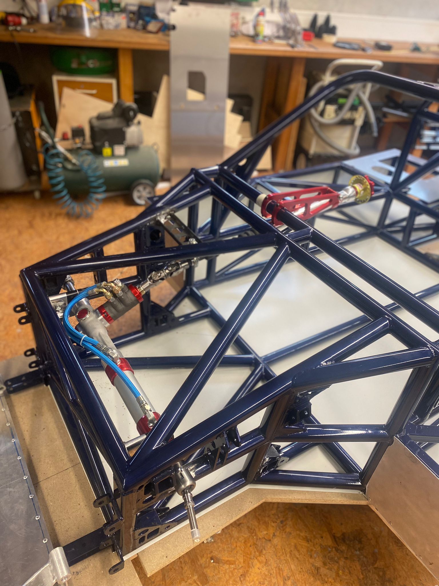
When designing the frame, it quickly became clear that the original, unchanged track width on the front axle in conjunction with the wide rims would lead to very short wishbones and track rods. This generates high steering forces, especially when using modern tires. Servo assistance was therefore indispensable – especially for a car that puts over 500 hp on the road.

I naturally opted for a power steering system from the racing world. This solution combines the best of both worlds: the direct and precise control I want with the necessary support to move the car safely and comfortably. After a lot of research and a few discussions with experts from racing teams, I chose the Woodward Precision Power Steering System.

Why Woodward?

  1. A flexible modular system: I am not aware of any other supplier that really offers such extensively customizable power steering systems for such projects.
    Woodward convinced me with their modular approach, which allowed me to customize the steering to the exact requirements of my car. This flexibility was the decisive point for me.
  2. Racing quality: Woodward stands for racing. Their products are not only developed for everyday use, but also for tough use on the race track. The fact that they were recently successful in the LMP2 class at Le Mans with the steering system I used shows how seriously they take their work – and that’s exactly what I wanted for my project.
  3. Perfect integration into the CAD model: A big plus point was that Woodward was the only company willing to provide me with a STEP file of their system. This file helped me immensely to integrate the steering system seamlessly into my CAD model and ensure that it fits perfectly.

I only had to fill out a data sheet with a few details, received the corresponding CAD file after 3 days and after only 3 weeks from the USA I have the steering system here in my workshop.

Choosing Woodward not only made technical sense, but also gave me the feeling that I had taken another important step towards my dream. I am always impressed by how much engineering skill goes into a system like this. I am sure that it will make a decisive contribution to making my GT40 MKIV a vehicle that not only looks like a racing car, but also feels like one.

Tuning the steering to the chassis geometry

Matching the steering to the chassis geometry is an extremely complex task. It’s not just about correctly calculating the Ackermann angle – the different steering geometry of the front wheels in a bend. Modern suspension designs take far more into account: for example, the steering angle of the front wheels changes during compression and rebound, ideally in such a way that the driving characteristics are improved.
Unwanted steering movements due to compression or rebound – the famous “bump steering” – must be avoided at all costs, as it significantly impairs cornering behavior and therefore driving safety.

These dynamic kinematics considerations are a field of their own that could be the subject of entire books – and that would go beyond the scope of this article. I must honestly admit that I couldn’t manage this task on my own. Fortunately, I was able to count on the support of my friend Uwe Bleck (kinematic engineer) for the steering geometry, who helped me considerably with his knowledge and experience. Finding the correct pivot points in space and designing the geometry in such a way that it fulfills both the historical charm and the requirements of a modern, high-performance vehicle was an enormous challenge.
It was already complicated enough for me to design the necessary pivot points on the wheel and frame.

Of course, the rear axle should not be forgotten, as the wheel is also held at the correct angle by a tie rod. With the correct arrangement of the mounting points, it is even possible to achieve that the rear wheels “steer” slightly when deflecting and thus further improve the riding characteristics.

The whole issue of suspension and steering is simply overwhelming. With over 25 degrees of freedom, you can quickly become dizzy. During the coronavirus pandemic, I spent months familiarizing myself with the system and now I just understand the basics. Even if you theoretically grasp everything, you simply don’t have the many thousands of hours of test work on the racetrack. I am convinced that only experts can solve this complex puzzle.

Without the help of my two friends Uwe Bleck and Andy Köhler, who don’t know each other, this would have been impossible for me. And if they did know each other, they would probably have endless discussions about which is better – and it often remains unclear who is actually right! 😊