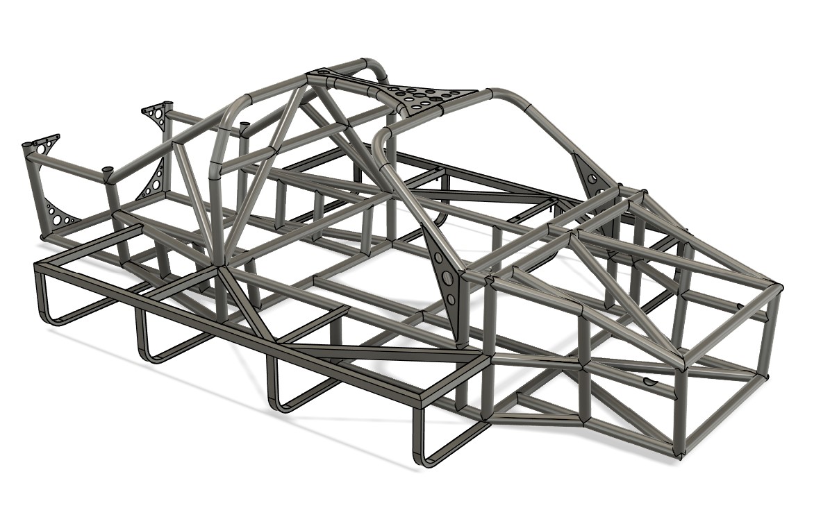
The chassis in detail: design and dimensioning


A chassis is not only the basis of a vehicle, but for me it was the key to combining tradition and innovation. When recreating this legendary racing car, my aim was to capture the technical dimensions and appearance of the original, while using modern production methods and materials to adapt the design to contemporary requirements.
- Creating the tubular lattice frame in CAD – what methods are available?
There are various ways of designing a tubular lattice frame in CAD, each of which has advantages and disadvantages. I have examined three common approaches:
Modeling with cylindrical solids:
Here, the pipes are modeled directly as cylindrical solids and joined together to form a frame. This method is simple and direct, but quickly reaches its limits with more complex designs, as adjustments are time-consuming and not very flexible.
Modeling with lines and extrusion:
A popular method is to first build the model with lines in 3D space that represent the centerlines of the pipes. Circles with the desired pipe cross-section are then extruded along these lines to create the pipes. The individual bodies are then adapted to each other using Boolean operations.
Use of special pipe bending modules in CAD:
Modern CAD programs often offer modules that have been specially developed for pipe designs. These make it easier to create complex bends and connections, but are often application- or industry-specific and require a certain amount of training.
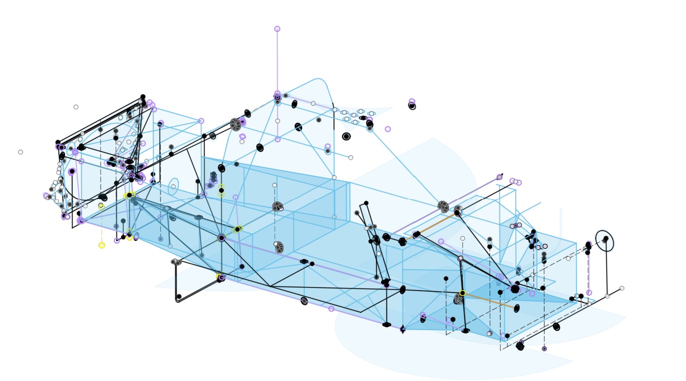
I opted for the second method because it was the easiest to implement with TurboCAD, which I used for the first drafts of the frame. This method gave me the necessary control over the geometry, while remaining flexible enough for customization.
I later switched to Fusion360 due to the simulation requirements and stuck with this approach. Fusion360 gave me the ability to organize the cross sections of the pipes into lists. This made it theoretically possible to make changes to pipe diameters efficiently – a valuable feature if you want to try out different variants during the simulation.
In practice, however, it turned out that this method quickly becomes very complex. For example, changes to the pipe diameter also affect the joints at the junctions. At the time, I did not manage to map the frame completely parametrically and thus generate variants. This was probably due to my limited knowledge of Fusion360 at the time.
If anyone knows how to solve this challenge elegantly, I’d really like to learn! - Dimensioning of pipes and material selection based on simulations
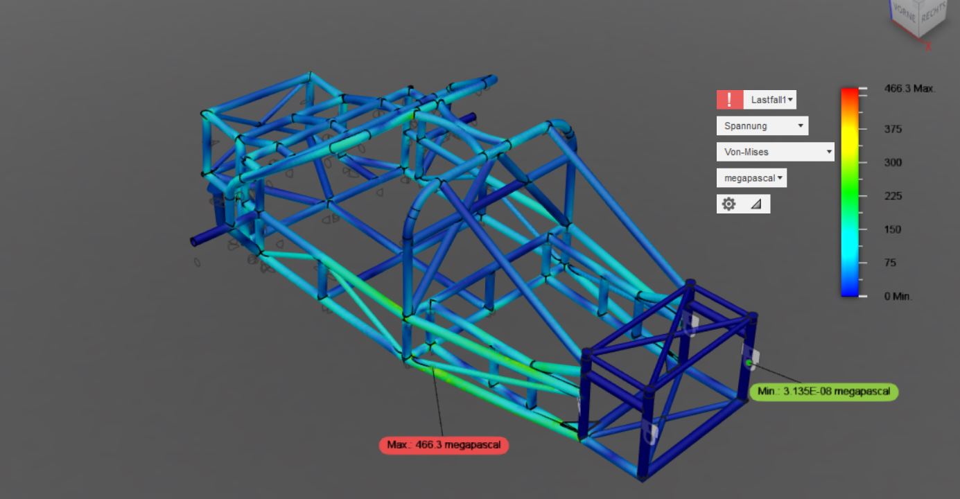
Fusion360 offers a powerful simulation module that makes it relatively easy to carry out FEM calculations. However, as is so often the case, the devil is in the detail, and I had to overcome numerous challenges, especially when dimensioning a tubular lattice frame.
The most difficult questions for me were:
- Fixed points on the frame: Where exactly should these be defined in order to simulate realistic conditions?
- Point of application and height of the load: How high is the load actually, for example when driving over a curb at 100 km/h? Such loads are difficult to estimate if no measured values are available.
- Mesh fineness of the simulation: How fine must the FEM mesh be in order to deliver precise results without unnecessarily increasing computing times?
- Safety factor: Which factor makes sense to factor in realistic reserves?
An additional problem arose from the geometry of my pipes: they taper at the junctions – often more sharply in CAD than is possible in reality. So-called “hotspots”, i.e. areas with extreme stress peaks, occur at these points. But are these realistic or an artifact of the simulation?
I would not have been able to overcome these challenges without external help. Fortunately, I had access to a valuable network:
- A structural steel engineer, who was also a client of mine, introduced me to the basics of statics. That helped me to overcome the first stumbling blocks.
- Andy Köhler from Motopark in Oschersleben was my most important support. As Technical Director of a successful racing team in formula racing and the GT3 class, Andy has invaluable knowledge. Thanks to his experience in vehicle construction and the use of sensors to measure peak loads on the racetrack, I was able to make my simulations much more realistic.
An important insight that I have gained through this collaboration:
Simulations are only as good as the underlying assumptions.
If these are wrong, the results are nothing more than colorful pictures with no practical value. In particular, the experience of an engineer who has spent countless hours on the racetrack cannot be replaced by software alone.
I can therefore only recommend having such simulations carried out by professionals if you do not have an appropriate network. It is money well spent, because familiarizing yourself with this subject is extremely time-consuming. It is also difficult to find reliable information, as a lot of racing know-how is closely guarded.
Beware of dangerous half-knowledge: Unrealistic advice often circulates on internet forums. Those who really know their stuff rarely comment publicly. Realistic load data is almost never shared, as it is an essential part of engineering know-how.
To summarize: without experienced support, my simulations would have been neither realistic nor feasible. Software alone is not enough – the combination of technical expertise and practical experience makes all the difference
3. the choice of pipe cross-section – a compromise between stability and manufacturability
During the development of the frame and the first simulations, I decided to replace the initially planned square tubes in the structurally highly stressed area of the cell with tubes with a round cross-section. There were several reasons for this change: Round tubes are more stable in all directions with the same material thickness and offer significant advantages, particularly in terms of energy absorption in the event of an accident.
But this decision brought with it new challenges:
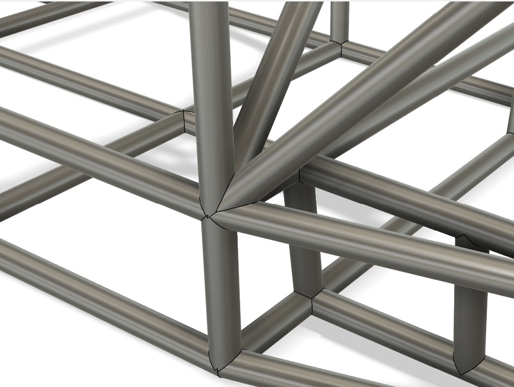
When I showed the first CAD images of my frame in the GT40s.com forum, an experienced forum user immediately pointed out the significantly higher complexity of building a frame from round tubes. Unlike rectangular or square tubes, which are quite easy to cut and adapt yourself, round tubes run to the center of the other tube at the transitions. This creates complex junctions, especially when several pipes meet. Although these are more stable, they are also more difficult to produce.
At first I dismissed this tip somewhat lightly, as I was planning to have the pipes cut to size using a CNC laser anyway. But as the work progressed, I came across another problem:
Cladding the pipes with aluminum sheet
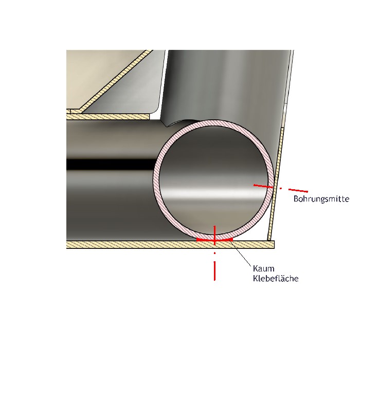
Attaching the aluminum sheets to round pipes proved to be unexpectedly challenging. For one thing, the bonding surface is smaller on round pipes than on square ones. Secondly, riveting presents additional difficulties:
- Precision when drilling: The drill bit must hit the highest point of the pipe exactly to prevent it from slipping. This was often a real test of patience, especially in hard-to-reach places, and the drill bit breaks quickly – not fun when the tip is deep in the pipe.
- Problems with slipping: The 25CrMo4 tube used is much harder than the aluminum sheet, which meant that a slipping drill quickly left an oval and therefore unusable hole in the aluminum sheet.
During the design phase, I decided to use rectangular tubes for the side boxes in which the tanks are housed. From a static point of view, these areas are only attached to the outside of the frame and are hardly stressed during normal driving. Right from the start, the focus here was on passive safety in the event of an accident – a topic that I will cover in more detail elsewhere.
Would I build my frame like this again?
Definitely. Despite the difficulties in production, the switch to round tubes in the central area of the cell was the right decision. Today, however, I would assess the challenges more realistically from the outset and plan more specifically. The gain in stability and safety is definitely worth the extra effort
Leave a Reply
You must be logged in to post a comment.