The frame construction


Tubes
First of all, I would like to briefly explain the different tubes that make up my tubular lattice frame.
For my frame I used 25CrMo4 tubes, which are widely used in racing. These tubes are readily available from specialized dealers for the motorsport sector. I bought mine from motorsport-metall.de, the web store belongs to the company TENNANT GmbH. The tubes are available in lengths of 4 – 6m.
The structural steel often used by replica builders has a tensile strength of 300-400 N/mm², whereas the tensile strength of 25CrMo4 is between 800-1000N/mm², i.e. more than twice as much!
This higher strength makes 25CrMo4 ideal for applications that require high load-bearing capacity, such as in motorsport.
Pipe dimensions used
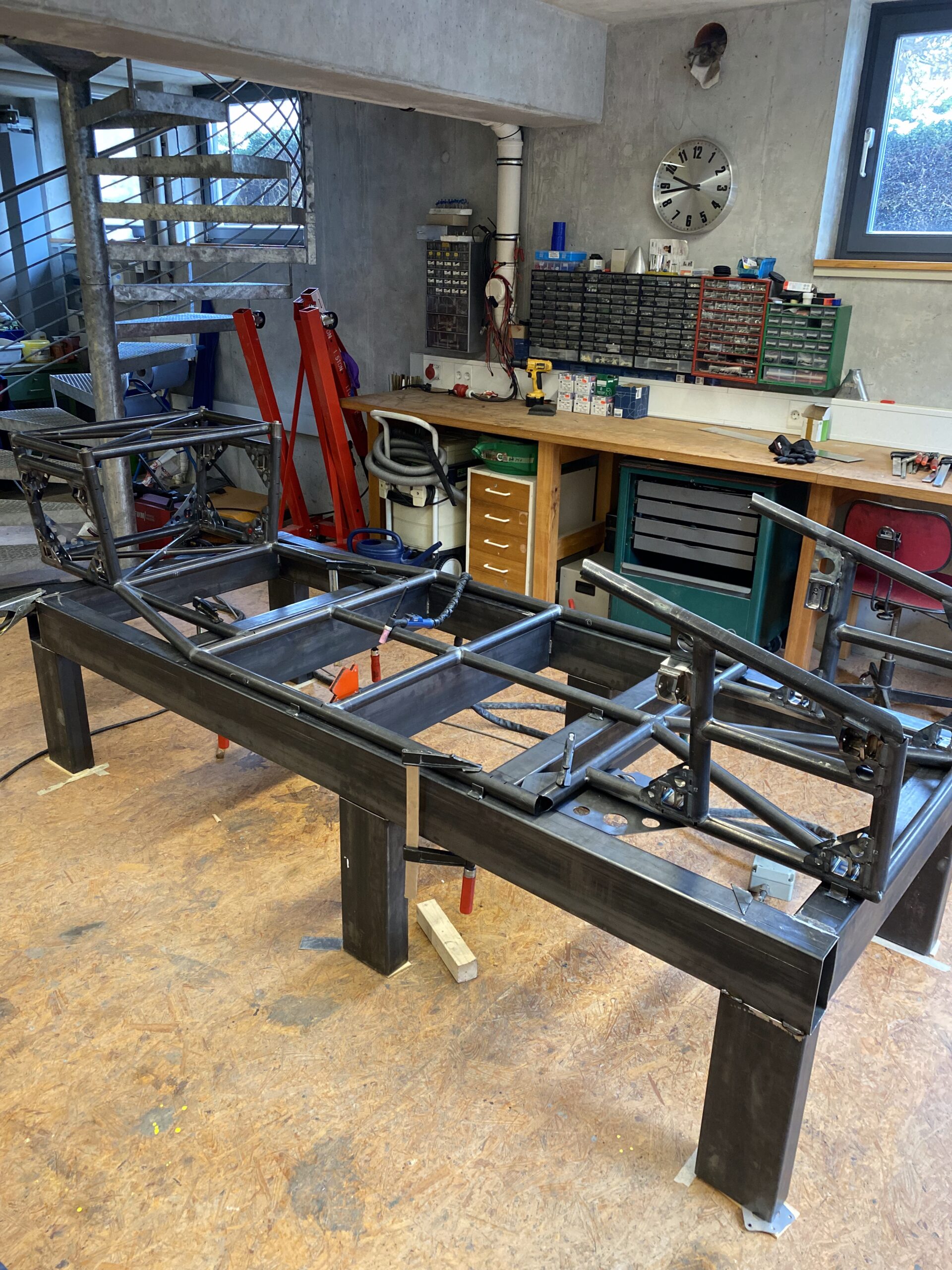
I mainly used 40×2 mm and 25×2 mm tubes, which are a common size in frame construction. In retrospect, 35×2 mm tubes might also have been sufficient. However, I would then have had to design and, above all, simulate a completely new version of the frame, which would have been too much work for me.
At the beginning, my frame weighed about 160 kg in the first designs in the CAD program. After more than 100 new designs with optimizations and simulations, I was able to reduce the weight to about 98 kg with the 40 mm tubes. The 35 mm tubes are around 14% lighter, which would have brought me down to around 85 kg. But I didn’t want to go to all the trouble of redoing everything.
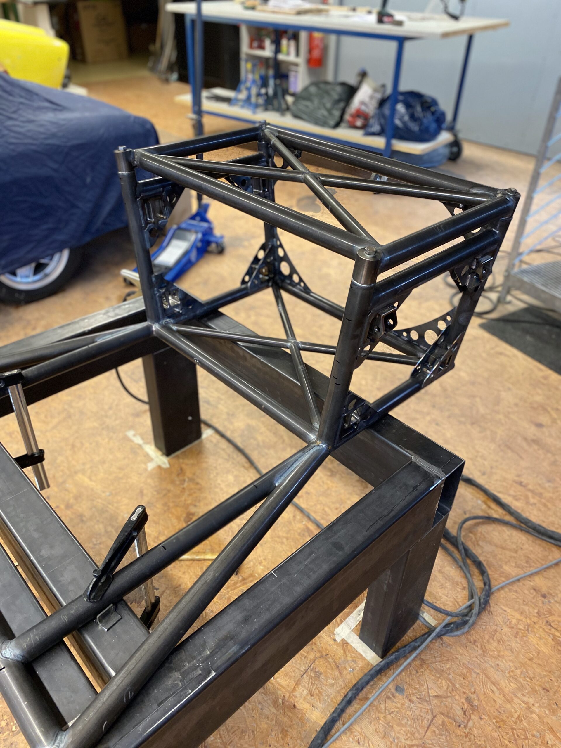
The 25×2 mm tubes were used for the tension struts for bracing. I built the two side boxes at the top from 30x30x2 mm square tubes, while the bent ribs are made from 30x15x2 mm tubes. These side boxes do not contribute to the rigidity of the actual frame and are therefore kept as simple as possible.
Precise cutting of the tubes
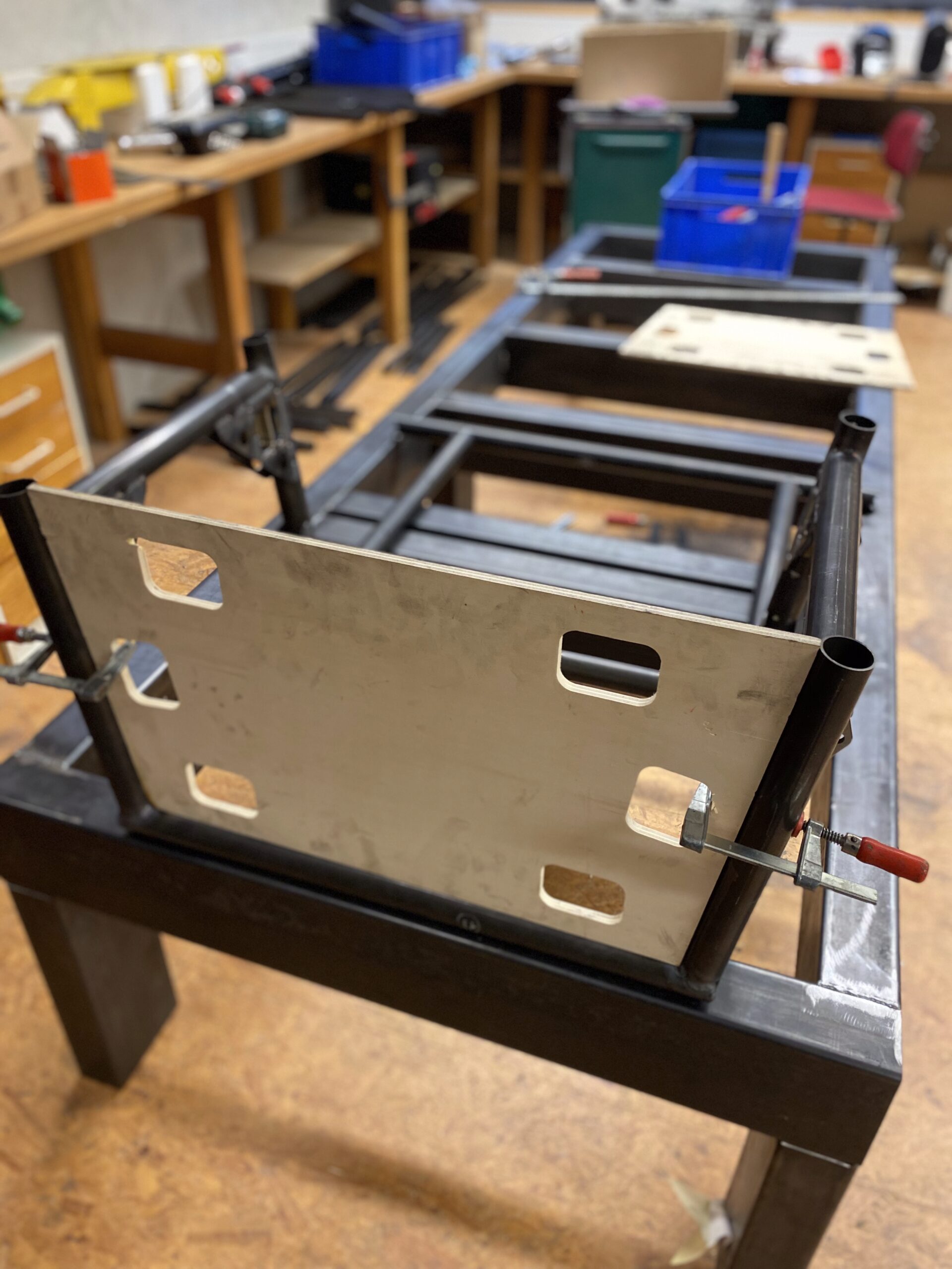
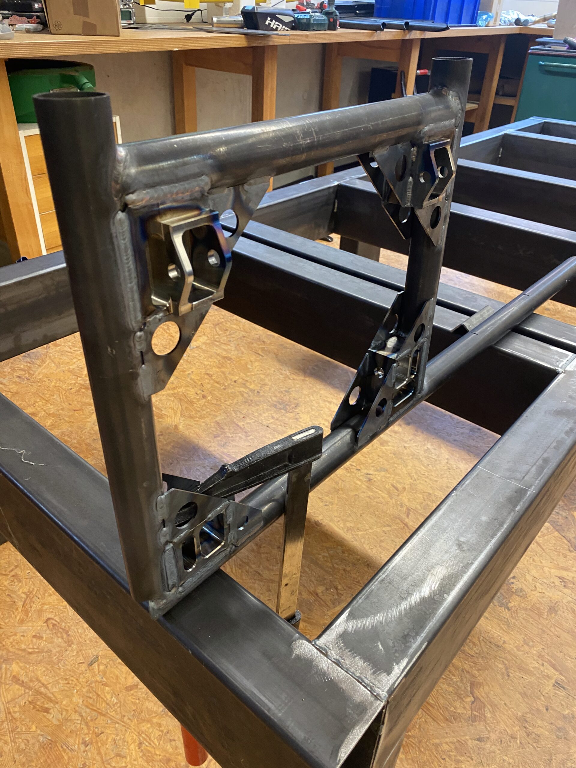
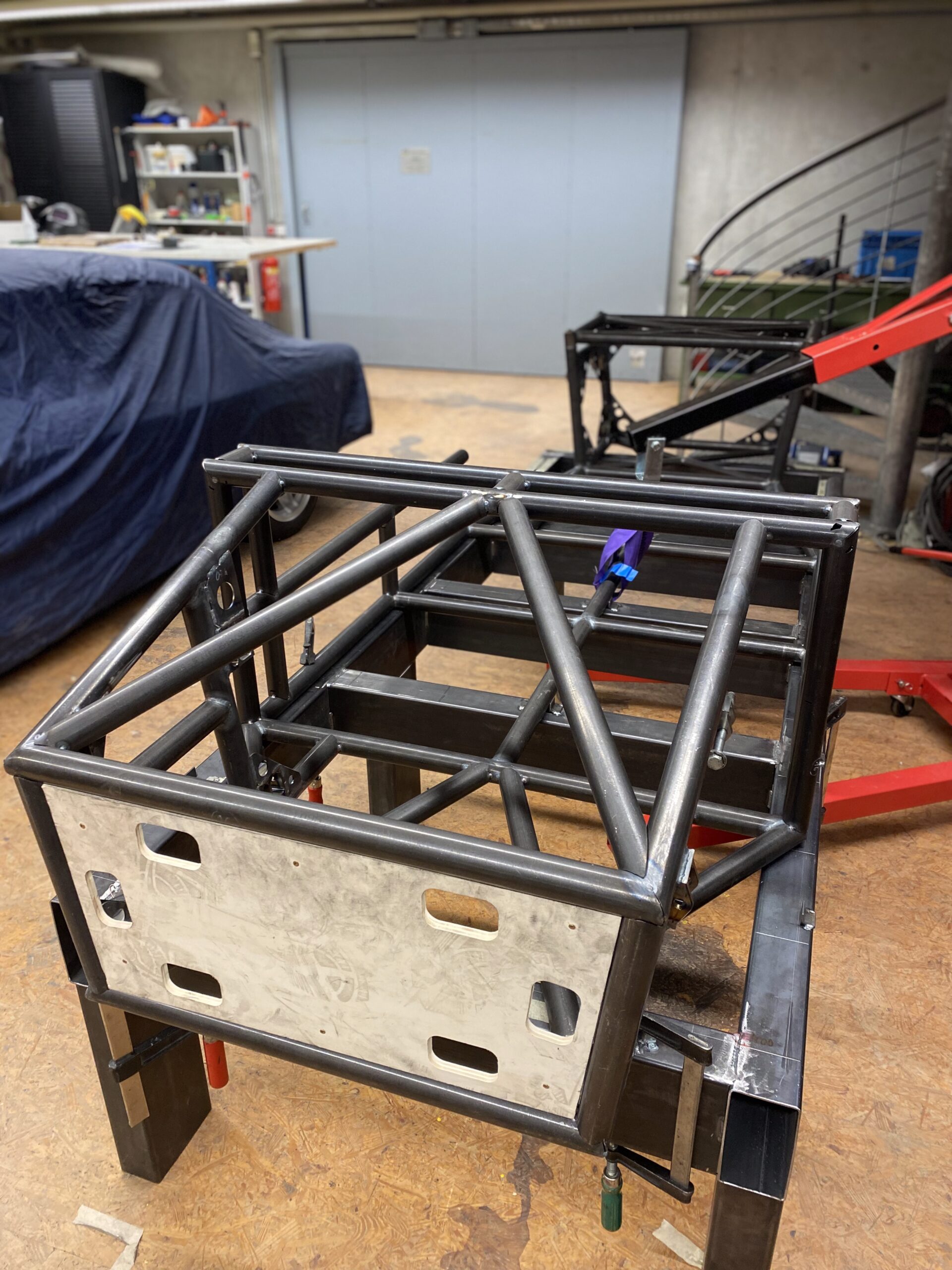
As already described in the corresponding article in the “Construction” section, I had all the tubes cut using a laser CNC machine. A big thank you goes to Alex, who even added small rectangular lugs to my CAD data that fit into corresponding cut-outs in the counterpart. This made alignment even easier – a great idea!
I also had to make an exploded view of the frame and assign a number to each tube. Alex then engraved these numbers into the individual tubes with a laser during the cutting process. However, the engraving was difficult to read on some of the tubes, which resulted in a lengthy search to find out where they belonged. The frame consists of almost 100 tubes, so it’s easy to lose track.
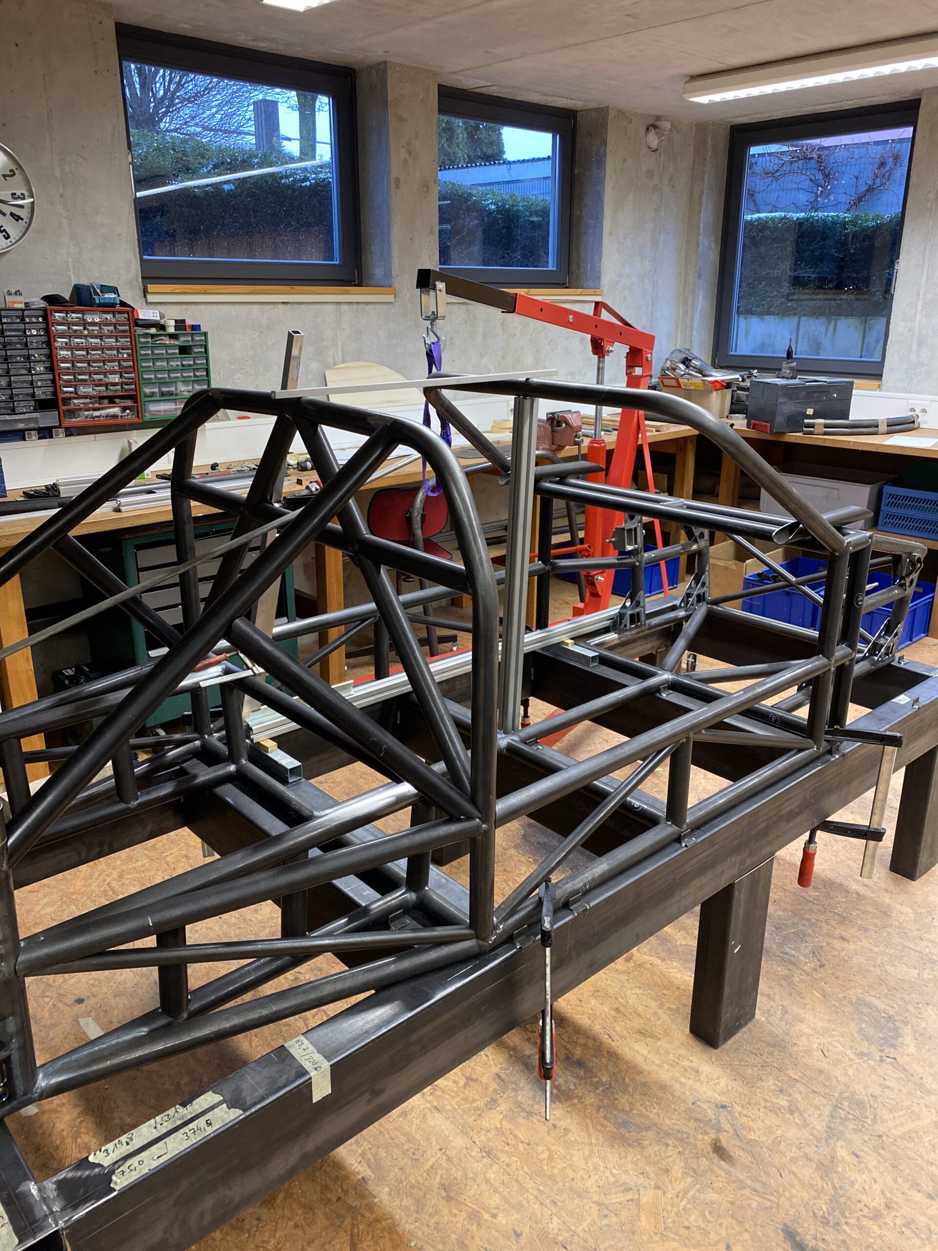
Welding the frame
Perhaps a few words about welding.
I can only do gas-shielded arc welding (MAG) myself, and not particularly well. However, the TIG process is usually used on frames like this. This is where I enlisted the help of my friend Erwin, a pensioner with a lot of time on his hands and plenty of experience. Watching him weld was a real pleasure. Not only that the weld seams look like each other, but especially the way he welds.
First weld on one half of a pipe, bending it in the direction of the weld seam, then let it cool down and weld the second half. And as if by magic, the pipe bends back into its original position – amazing! That takes decades of experience.
Stress-free annealing of the frame
I actually wanted to let the frame anneal stress-free after welding. But firstly, I couldn’t find an oven that would fit my frame, and secondly, this was at a time when energy prices were skyrocketing. The suppliers almost tripled their prices within a few months.
Conclusion
To build such a frame, you need a lot of skills and knowledge, although it remains to be seen whether you really have to do it as elaborately as I did.
I am more than satisfied with the result and would like to thank Erwin and Alex once again!


Leave a Reply
You must be logged in to post a comment.